Aerodynamic center

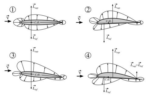
In aerodynamics, the torques or moments acting on an airfoil moving through a fluid can be accounted for by the net lift and net drag applied at some point on the airfoil, and a separate net pitching moment about that point whose magnitude varies with the choice of where the lift is chosen to be applied. The aerodynamic center is the point at which the pitching moment coefficient for the airfoil does not vary with lift coefficient (i.e. angle of attack), making analysis simpler.[1]
- [math]\displaystyle{ {dC_m\over dC_L} =0 }[/math] where [math]\displaystyle{ C_L }[/math] is the aircraft lift coefficient.
The lift and drag forces can be applied at a single point, the center of pressure, about which they exert zero torque. However, the location of the center of pressure moves significantly with a change in angle of attack and is thus impractical for aerodynamic analysis. Instead the aerodynamic center is used and as a result the incremental lift and drag due to change in angle of attack acting at this point is sufficient to describe the aerodynamic forces acting on the given body.
Theory
Within the assumptions embodied in thin airfoil theory, the aerodynamic center is located at the quarter-chord (25% chord position) on a symmetric airfoil while it is close but not exactly equal to the quarter-chord point on a cambered airfoil.
From thin airfoil theory:[2]
- [math]\displaystyle{ \ c_l = 2\pi \alpha }[/math]
- where [math]\displaystyle{ c_l\! }[/math] is the section lift coefficient,
- [math]\displaystyle{ \alpha\! }[/math] is the angle of attack in radian, measured relative to the chord line.
- [math]\displaystyle{ \ {dc_{m,c/4} \over d\alpha} = m_0 }[/math]
- where [math]\displaystyle{ \ c_{m,c/4} }[/math] is the moment taken at quarter-chord point and [math]\displaystyle{ \ m_0 }[/math] is a constant.
- [math]\displaystyle{ \ M_{ac} = L ( c x_{ac} - c/4)+M_{c/4} }[/math]
- [math]\displaystyle{ \ c_{m,ac} = c_l (x_{ac} - 0.25)+c_{m,c/4} }[/math]
Differentiating with respect to angle of attack
- [math]\displaystyle{ \ x_{ac} = {- m_0 \over {2\pi}} + 0.25 }[/math]
For symmetrical airfoils [math]\displaystyle{ \ m_0 = 0 }[/math], so the aerodynamic center is at 25% of chord. But for cambered airfoils the aerodynamic center can be slightly less than 25% of the chord from the leading edge, which depends on the slope of the moment coefficient, [math]\displaystyle{ \ m_0 }[/math]. These results obtained are calculated using the thin airfoil theory so the use of the results are warranted only when the assumptions of thin airfoil theory are realistic. In precision experimentation with real airfoils and advanced analysis, the aerodynamic center is observed to change location slightly as angle of attack varies. In most literature however the aerodynamic center is assumed to be fixed at the 25% chord position.
Role of aerodynamic center in aircraft stability
For longitudinal static stability:
- [math]\displaystyle{ \frac{dC_m}{d\alpha} \lt 0 \quad \text{and} \quad \frac{dC_z}{d\alpha} \gt 0 }[/math]
For directional static stability:
- [math]\displaystyle{ \frac{dC_n}{d\beta} \gt 0 \quad \text{and} \quad \frac{dC_y}{d\beta} \lt 0 }[/math]
Where:
- [math]\displaystyle{ C_z = C_L \cos(\alpha) + C_d \sin(\alpha) }[/math]
- [math]\displaystyle{ C_x = C_L \sin(\alpha) - C_d \cos(\alpha) }[/math]
For a force acting away from the aerodynamic center, which is away from the reference point:
- [math]\displaystyle{ X_{AC} = X_\mathrm{ref} + c{dC_m\over dC_z} }[/math]
Which for small angles cos(α) = 1 and sin(α) = α, β = 0, [math]\displaystyle{ C_z=C_L-C_d*\alpha, }[/math] [math]\displaystyle{ C_z=C_L }[/math] simplifies to:
- [math]\displaystyle{ \begin{align} & X_{AC} = X_\mathrm{ref} + c{dC_m\over dC_L} \\ & Y_{AC} = Y_\mathrm{ref} \\ & Z_{AC} = Z_\mathrm{ref} \end{align} }[/math]
General Case: From the definition of the AC it follows that
- [math]\displaystyle{ \begin{align} & X_{AC} = X_\mathrm{ref} + c{dC_m\over dC_z} + c{dC_n\over dC_y} \\ & Y_{AC} = Y_\mathrm{ref} + c{dC_l\over dC_z} + c{dC_n\over dC_x} \\ & Z_{AC} = Z_\mathrm{ref} + c{dC_l\over dC_y} + c{dC_m\over dC_x} \end{align} }[/math]
The Static Margin can then be used to quantify the AC:
- [math]\displaystyle{ SM = {X_{AC} - X_{CG}\over c} }[/math]
where:
- Cn = yawing moment coefficient
- Cm = pitching moment coefficient
- Cl = rolling moment coefficient
- Cx = X-force ≈ Drag
- Cy = Y-force ≈ Side Force
- Cz = Z-force ≈ Lift
- ref = reference point (about which moments were taken)
- c = reference length
- S = reference area
- q = dynamic pressure
- α = angle of attack
- β = sideslip angle
- SM = Static Margin
See also
- Aircraft flight mechanics
- Flight dynamics
- Longitudinal static stability
- Thin-airfoil theory
- Joukowsky transform
References
- ↑ Benson, Tom (2006). "Aerodynamic Center (ac)". The Beginner's Guide to Aeronautics. NASA Glenn Research Center. http://www.grc.nasa.gov/WWW/K-12/airplane/ac.html. Retrieved 2006-04-01.
- ↑ Anderson, John David Jr. (12 February 2010). Fundamentals of aerodynamics (Fifth ed.). New York. ISBN 9780073398105. OCLC 463634144.
 |

