Engineering:Flyback diode
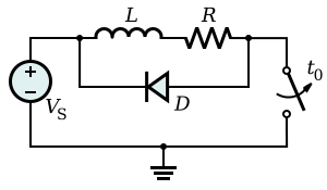
A flyback diode is any diode connected across an inductor used to eliminate flyback, which is the sudden voltage spike seen across an inductive load when its supply current is suddenly reduced or interrupted. It is used in circuits in which inductive loads are controlled by switches, and in switching power supplies and inverters.
Flyback circuits have been used since 1930 and were refined starting in 1950 for use in television receivers. The word flyback comes from the horizontal movement of the electron beam in a cathode ray tube, because the beam flew back to begin the next horizontal line.[1][2]
This diode is known by many other names, such as snubber diode, commutating diode, freewheeling diode, suppressor diode, clamp diode, or catch diode.[3][4]
Operation
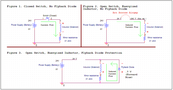
Fig. 1 shows an inductor connected to a battery - a constant voltage source. The resistor represents the small residual resistance of the inductor's wire windings. When the switch is closed, the voltage from the battery is applied to the inductor, causing current from the battery's positive terminal to flow down through the inductor and resistor.[5][6] The increase in current causes a back EMF (voltage) across the inductor due to Faraday's law of induction which opposes the change in current. Since the voltage across the inductor is limited to the battery's voltage of 24 volts, the rate of increase of the current is limited to an initial value of [math]\displaystyle{ {dI \over dt} = {V_B \over L}, }[/math] so the current through the inductor increases slowly as energy from the battery is stored in the inductor's magnetic field. As the current rises, more voltage is dropped across the resistor and less across the inductor, until the current reaches a steady value of [math]\displaystyle{ I = V_B/R }[/math] with all the battery voltage across the resistance and none across the inductance.
However, the current drops rapidly when the switch is opened in Fig. 2. The inductor resists the drop in current by developing a very large induced voltage of polarity in the opposite direction of the battery, positive at the lower end of the inductor and negative at the upper end.[5][3][6] This voltage pulse, sometimes called the inductive "kick", which can be much larger than the battery voltage, appears across the switch contacts. It causes electrons to jump the air gap between the contacts, causing a momentary electric arc to develop across the contacts as the switch is opened. The arc continues until the energy stored in the inductor's magnetic field is dissipated as heat in the arc. The arc can damage the switch contacts, causing pitting and burning, eventually destroying them. If a transistor is used to switch the current, such as switching power supplies, the high reverse voltage can destroy the transistor.
To prevent the inductive voltage pulse on turnoff, a diode is connected across the inductor, as shown in Fig. 3.[5][3][6] The diode doesn't conduct current while the switch is closed because it is reverse-biased by the battery voltage, so it doesn't interfere with the normal operation of the circuit. However, when the switch is opened, the induced voltage across the inductor of opposite polarity forward biases the diode, and it conducts current, limiting the voltage across the inductor and thus preventing the arc from forming at the switch. The inductor and diode momentarily form a loop or circuit powered by the stored energy in the inductor. This circuit supplies a current path to the inductor to replace the current from the battery, so the inductor current does not drop abruptly and does not develop a high voltage. The voltage across the inductor is limited to the forward voltage of the diode, around 0.7 - 1.5V. This "freewheeling" or "flyback" current through the diode and inductor decreases slowly to zero as the magnetic energy in the inductor is dissipated as heat in the series resistance of the windings. This may take a few milliseconds in a small inductor.
These images show the voltage spike and its elimination through the use of a flyback diode (1N4007). In this case, the inductor is a solenoid connected to a 24V DC power supply. Each waveform was taken using a digital oscilloscope set to trigger when the voltage across the inductor dipped below zero. Note the different scaling: left image 50V/division, right image 1V/division. In Figure 1, the voltage as measured across the switch, bounces/spikes to around -300 V. In Figure 2, a flyback diode was added in antiparallel with the solenoid. Instead of spiking to -300 V, the flyback diode only allows approximately -1.4 V of potential to be built up (-1.4 V is a combination of the forward bias of the 1N4007 diode (1.1 V) and the foot of wiring separating the diode and the solenoid[dubious ]). The waveform in Figure 2 is also smoother than the waveform in Figure 1, perhaps due to arcing at the switch for Figure 1. In both cases, the total time for the solenoid to discharge is a few milliseconds, though the lower voltage drop across the diode will slow relay dropout.
Design
When used with a DC coil relay, a flyback diode can cause delayed drop-out of the contacts when power is removed, due to the continued circulation of current in the relay coil and diode. When rapid opening of the contacts is important, a resistor or reverse-biased Zener diode can be placed in series with the diode to help dissipate the coil energy faster, at the expense of higher voltage at the switch.
Schottky diodes are preferred in flyback diode applications for switching power converters because they have the lowest forward drop (~0.2 V rather than >0.7 V for low currents) and are able to quickly respond to reverse bias (when the inductor is being re-energized). They, therefore, dissipate less energy while transferring energy from the inductor to a capacitor.
Induction at the opening of a contact
According to Faraday's law of induction, if the current through an inductance changes, this inductance induces a voltage, so the current will flow as long as there is energy in the magnetic field. If the current can only flow through the air, the voltage is so high that the air conducts. That is why in mechanically switched circuits, the near-instantaneous dissipation which occurs without a flyback diode is often observed as an arc across the opening mechanical contacts. Energy is dissipated in this arc primarily as intense heat, which causes undesirable premature erosion of the contacts. Another way to dissipate energy is through electromagnetic radiation.
Similarly, for non-mechanical solid-state switching (i.e., a transistor), large voltage drops across an unactivated solid-state switch can destroy the component in question (either instantaneously or through accelerated wear and tear).
Some energy is also lost from the system as a whole and from the arc as a broad spectrum of electromagnetic radiation, in the form of radio waves and light. These radio waves can cause undesirable clicks and pops on nearby radio receivers.
To minimise the antenna-like radiation of this electromagnetic energy from wires connected to the inductor, the flyback diode should be connected as physically close to the inductor as practicable. This approach also minimises those parts of the circuit that are subject to an unwanted high-voltage — a good engineering practice.
Derivation
The voltage at an inductor is, by the law of electromagnetic induction and the definition of inductance:
- [math]\displaystyle{ V_L = - {d\Phi_B \over dt} = - L {dI \over dt} }[/math]
If there is no flyback diode but only something with great resistance (such as the air between two metal contacts), say, R2, we will approximate it as:
- [math]\displaystyle{ V_{R_2} = R_2 \cdot I }[/math]
If we open the switch and ignore VCC and R1, we get:
- [math]\displaystyle{ V_L = V_{R_2} }[/math]
or
- [math]\displaystyle{ - L {dI \over dt} = R_2 \cdot I }[/math]
which is a differential equation with the solution:
- [math]\displaystyle{ I(t) = I_0 \cdot e^{- {R_2 \over L} t} }[/math]
We observe that the current will decrease faster if the resistance is high, such as with air.
Now if we open the switch with the diode in place, we only need to consider L1, R1 and D1. For I > 0, we can assume:
- [math]\displaystyle{ V_D = \mathrm{constant} }[/math]
so:
- [math]\displaystyle{ V_L = V_{R_1} + V_D }[/math]
which is:
- [math]\displaystyle{ - L {dI \over dt} = R_1 \cdot I + V_D }[/math]
whose (first order differential equation) solution is:
- [math]\displaystyle{ I(t) = (I_0+{1\over R_1} V_D) \cdot e^{- {R_1 \over L} t} - {1 \over R_1} V_D }[/math]
We can calculate the time it needs to switch off by determining for which t it is I(t) = 0.
- [math]\displaystyle{ t = {-L\over R_1} \cdot ln{\left({V_D \over {V_D + I_0{R_1}}}\right)} }[/math]
If VCC = I0R1, then
- [math]\displaystyle{ t = {-L\over R_1} \cdot ln{\left({1 \over {\frac{V_{CC}}{V_D} + 1}}\right)}={L\over R_1} \cdot ln{\left({{\frac{V_{CC}}{V_D} + 1}}\right)} }[/math]
Applications
Flyback diodes are commonly used when semiconductor devices switch inductive loads off: in relay drivers, H-bridge motor drivers, and so on. A switched-mode power supply also exploits this effect, but the energy is not dissipated to heat and is instead used to pump a packet of additional charge into a capacitor, in order to supply power to a load.
When the inductive load is a relay, the flyback diode can noticeably delay the release of the relay by keeping the coil current flowing longer. A resistor in series with the diode will make the circulating current decay faster at the drawback of an increased reverse voltage. A zener diode in series but with reverse polarity with regard to the flyback diode has the same properties, albeit with a fixed reverse voltage increase. Both the transistor voltages and the resistor or zener diode power ratings should be checked in this case.
See also
References
- ↑ Schweber, Bill (December 10, 2019). "The Flyback Power-Supply Architecture and Operation". Endeavor Business Media. https://www.electronicdesign.com/12345/whitepaper/21808957/the-flyback-powersupply-architecture-and-operation.
- ↑ "Introduction to Flyback Transformer". Utmel Electronics. January 29, 2021. https://www.utmel.com/blog/categories/transformers/introduction-to-flyback-transformer.
- ↑ 3.0 3.1 3.2 Wilcher, Don (2012). Learn Electronics with Arduino. Apress. pp. 74–75. ISBN 978-1430242673. https://books.google.com/books?id=NiFpaZFqzRsC&pg=PA74. Retrieved 2020-05-14.
- ↑ Agarwal, Tarun (2016-08-26). "Freewheeling or Flyback Diode Working and Their Functions". https://www.elprocus.com/freewheeling-or-flyback-diode-circuit-working-functions/. Retrieved 21 May 2018.
- ↑ 5.0 5.1 5.2 Herrick, Robert J. (2003). DC/AC Circuits and Electronics: Principles & Applications. Cengage Learning. pp. 879–881. ISBN 0766820831. https://books.google.com/books?id=E_wKgWBu8rUC&dq=%22flyback+diode%22+inductor&pg=PA880.
- ↑ 6.0 6.1 6.2 Jacob, J. (2001). Power Electronics: Principles and Applications. Cengage Learning. pp. 292–294. ISBN 0766823326. https://books.google.com/books?id=FSpC6yNyNWcC&dq=flyback+diode&pg=PA293.
Further reading
- Ott, Henry (1988). Noise Reduction Techniques in Electronic Systems (2nd ed.). Wiley. ISBN 978-0471850687.
External links
- Relay Technical Notes - American Zettler
- Relay Application Notes - TE Connectivity
- Relay RC Circuit - Evox Rifa
- Application Circuits of Miniature Signal Relays - NEC/Tokin
- Diode Turn-on/off Time and Relay Snubbing - Clifton Laboratories
- "diode for relay coil spikes and motor shutoff spikes?" - sci.electronics.design
- Flyback Switch Mode Regulator Calculator - All About Circuits
 |


