Engineering:Differential screw


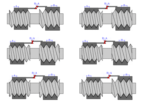
A differential screw is a mechanism used for making small, precise adjustments to the spacing between two objects (such as in focusing a microscope,[2] moving the anvils of a micrometer,[3][4] or positioning optics[5]). A differential screw uses a spindle with two screw threads of differing leads (in case of a single lead equal to the thread pitch), and possibly opposite handedness, on which two nuts move. As the spindle rotates, the space between the nuts changes based on the difference between the threads. These mechanisms allow extremely small adjustments using commonly available screws. A differential screw mechanism using two nuts incurs higher friction and therefore requires more torque to turn than a simple, single lead screw with an equivalent pitch.[6][7][8]
History
The first known use of a differential screw was on Towneley’s version of Gascoigne’s Micrometer.
Flamsteed’s Preface to the Historia Coelestis Britannica:
"Richard Towneley ... carried forward and completed his instrument (the micrometer) and made it perform with one screw, what on Gascoigne’s instrument had required two.” [9]
A drawing by Robert Hooke in 1667 clearly shows Towneley’s Micrometer with the single screw with two different pitch threads on it. With this differential screw, one thread was half the pitch of the other, Towneley was able to keep the micrometer's indicating pointers centered in the field of view as they opened and closed. [10]
Examples
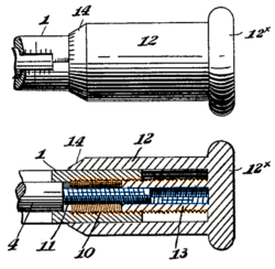
Many differential screw configurations are possible. The micrometer adjuster pictured uses a nut sleeve with different inner and outer thread pitches to connect a screw on the adjusting rod end with threads inside the main barrel; as the thimble rotates the nut sleeve, the rod and barrel move relative to each other based on the differential between the threads.
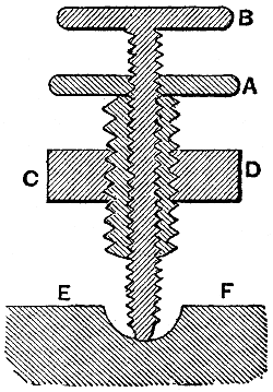
Another arrangement holds the two "nuts" co-axially in a single fixture and has two separate screws with slightly different pitches (distance from the crest of one thread to the next) entering from opposite ends. The "heads" of the screws are fixed to the two objects whose spacing is to be adjusted. Each rotation of the fixture holding the nuts moves one screw into its nut by a small amount and moves the other screw out of its nut by a slightly larger amount. The total spacing between the screws, and thus the objects, will be slightly changed based on the difference in travel between the two screws.
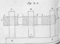
More arrangements are possible. Two nuts can be fixed to each of two objects to be adjusted and the two screw heads attached to each other in the middle. The combined screws would be turned to adjust the spacing in that case.[1]
Calculating motion and effective thread pitch
For single start threads, each turn changes the distance between the nuts by the effective pitch, Peff. For a bolt with a given thread per inch, TPI1 on one end and a second thread per inch, TPI2 on the other, the change in distance (or Peff), and the effective thread per inch TPIeff , is calculated by:
1/TPI1 - 1/TPI2 = 1/TPIeff = Peff[11]
For example, a bolt with coarse threads (16 tpi, 0.0625 in [1.59 mm] per turn) on one end and fine threads (24 tpi, 0.0416 in [1.06 mm] per turn) on the other changes the distance between the nuts by about 0.02 inches (0.51 mm) per revolution and is equivalent to a 48 tpi (0.53 mm/thread) thread:
1/16 - 1/24 = 0.0208 in. (48 tpi, 0.53 mm/thread)
For single start Metric threads, the effective pitch is simply the difference between the two thread pitches:
Pitch1 - Pitch2 = Pitcheff
For example, an M5x0.80 thread paired with an M4x0.70 thread will produce a differential motion of 0.1 mm, or 100 microns per revolution.
Mixing metric and imperial threads can result in finer differentials while still using standard threads, they can be calculated in the same way as a metric differential but the TPI of the imperial thread must be converted to a metric pitch measurement. For example a 26 TPI thread has a pitch of ~0.977mm and when paired with a 1.0mm pitch metric thread the differential motion will be approximately 0.023mm per revolution.
References
- ↑ 1.0 1.1 José María de Lanz; Agustín de Betancourt (1817). Analytical essay on the construction of machines: translated from the French of M.M. Lanz and Bétancourt. London: R. Ackermann. pp. 14–15, 181 Plate 1 fig D3. http://ebooks.library.cornell.edu/cgi/t/text/text-idx?c=kmoddl;cc=kmoddl;view=toc;subview=short;idno=kmod019.
- ↑ "A ONE-DOLLAR COMPOUND MICROSCOPE"
- ↑ US patent 343478, McArthur, Duncan, "Micrometer Calipers", issued 1880-02-08
- ↑ "Micrometer Heads Series 110-Differential Screw Translator (extra-Fine Feeding) Type". Product Catalog. Mitutoyo, U.S.A.. http://www.mitutoyo.com/TerminalMerchandisingGroup.aspx?group=1560.
- ↑ "Tutorials: Opto-Mechanical Components, Translation Stages, Drive Options". http://www.newport.com/servicesupport/Tutorials/default.aspx?id=91.
- ↑ "Screw Threads - The Theory Of Machines - Engineering Reference with Worked Examples". http://www.codecogs.com/reference/engineering/the_theory__of__machines/screw_threads.php#sec8.
- ↑ Kostelnicek, Dick (March 2010). "That Ol' Differential Screw Clamp". Home Metal Shop Club Newsletter 5 (3): 5–6. http://www.homemetalshopclub.org/news/10/newsletter1003.pdf#page=5. Retrieved 2012-12-24.
- ↑ Kuhrt, O.C. (1916). "A Toolmaker's Novel Clamp". American Machinist 44: 32. https://books.google.com/books?id=ZW8fAQAAMAAJ&dq=clamp&pg=PA32.
- ↑ Williams, Mari E. W. (1985). "John Flamsteed, Preface to Historia Coelestis Britannica. Edited and introduced by Allan Chapman, based on a translation by Alison Dione Johnson. Greenwich: National Maritime Museum, Maritime Monographs and Reports, No. 52, 1982. Pp. vi + 222. ISBN 0-905555-60-0. No price given.". The British Journal for the History of Science 18 (1): 103–103. doi:10.1017/s0007087400021890. ISSN 0007-0874.
- ↑ "The Antiquarian Astronomer, June 2016 p. 38". https://societyforthehistoryofastronomy.com/wp-content/uploads/2018/07/aa10.pdf.
- ↑ Yoder, Paul R. Jr. (2005). Opto-Mechanical System Design, Third Edition. CRC Press. p. 247. ISBN 1420027239.
 |


