Engineering:Lake discharge problem
A common open channel flow problem is determining the discharge from a lake to a rectangular channel.
Introduction
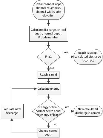
A lake discharges to a rectangular channel with a given width, hydraulic roughness and slope. Discharge at the lake outlet will vary based on the normal depth calculated from the lake and channel characteristics. Channel roughness is a characteristic described by the Gauckler–Manning coefficient (also called Manning's n). Channel roughness can be determined using Manning's Roughness Coefficients which describes the channel in terms of vegetation and size of bed sediment. Channel slope can be found using topographic maps to determine changes in elevation along the channel. The level of the lake (y) above the outlet is used for determining discharge, and can be determined by measuring the lake level relative to the channel bottom. The normal depth is the depth of water under conditions of uniform flow. Figure 1 provides a visual representation of the steps described above to determine the discharge at a lake outlet.
Determining discharge to a steep reach
Given the slope, roughness coefficient, channel width, and lake depth at the outlet, discharge to the channel can be calculated. Assuming the reach is steep, the channel is rectangular, the flow at the lake outlet is critical and the elevation of the lake relative to the outlet invert elevation is equal to the critical energy at the lake outlet.
- [math]\displaystyle{ y_c = {2 \over 3} E_\text{lake} \,\! }[/math] (Eq 1)
where:
- [math]\displaystyle{ y_c\, }[/math] is the critical depth (L)
- [math]\displaystyle{ E_\text{lake}, }[/math] is lake level relative to outlet invert (L)
Critical depth can be used to determine the specific discharge, q, the discharge per unit width in a rectangular channel. Specific discharge is multiplied by the width (b) to determine the discharge, Q. Equation 2 shows the formula for specific discharge.
- [math]\displaystyle{ q=\sqrt{y_c^3 g} }[/math] (Eq 2)
- [math]\displaystyle{ Q=qb }[/math] (Eq 3)
where:
- [math]\displaystyle{ q\, }[/math] is the specific discharge (L2/t)
- [math]\displaystyle{ y_c\, }[/math] is the critical depth (L)
- [math]\displaystyle{ g\, }[/math] is the force due to gravity (L/t2)
- [math]\displaystyle{ Q\, }[/math] is the discharge (L3/t)
- [math]\displaystyle{ b\, }[/math] is the channel width (L)
Normal depth is the depth of flow in a channel under uniform flow conditions. Normal depth occurs when the driving force of gravity is just balanced by the frictional force of drag along the channel sides and bottom. Normal depth is needed to solve for the discharge. To do this, the Manning formula for velocity, described below in Equation 4 can be used. The subsequent discharge can be determined by multiplying this velocity by the cross sectional area of the channel.
- [math]\displaystyle{ v={1.49 \over n}R^{2 \over 3} S^{1 \over 2} }[/math] (Eq 4)
where:
- [math]\displaystyle{ v\, }[/math] is the velocity of the flow (L/t)
- [math]\displaystyle{ R\, }[/math] is the hydraulic radius (L)
- [math]\displaystyle{ S\, }[/math]is the slope (L/L)
- [math]\displaystyle{ n\, }[/math] is Manning’s roughness coefficient
Normal depth is a function of channel geometry, roughness n, slope, and discharge. Therefore, an iterative method is needed to solve for normal depth in the rectangular channel. To determine whether the reach is steep, either the Froude number or a comparison of critical depth and normal depth can be used. The Froude number can be determined with the following equation:
- [math]\displaystyle{ Fr={v \over \sqrt{gy_0}} }[/math] (Eq 5)
where:
- [math]\displaystyle{ Fr\, }[/math] is the Froude number
- [math]\displaystyle{ v\, }[/math] is velocity in (L/t)
- [math]\displaystyle{ g\, }[/math] is the force due to gravity in (L/t2)
- [math]\displaystyle{ y_0\, }[/math] is the normal depth of water in (L)
If the Froude number is greater than 1, the flow is supercritical and the reach is steep. The discharge remains the same for a steep reach with a defined set of lake and reach characteristics. Therefore, the initial assumption in Equation 1 is valid and the solution has been found. The reach can also be classified as steep if the critical depth is greater than the normal depth.
Determining discharge to a mild reach
Changing any one of the channel characteristics may affect whether the reach is steep or mild. When the flow is subcritical, defined by a Froude number less than 1, the reach is mild. To traverse from a steep reach to a mild reach, the flow must pass through critical conditions. Critical conditions occur when the Froude number is equal to one.
In many cases, the discharge and normal depth for a mild slope will not initially be known. The discharge can be calculated through an iterative process. First, a discharge must be assumed so that the normal depth can be calculated. The following equation solves for discharge in terms of velocity and area. Normal depth is a function of both velocity and area and can therefore be solved using this equation.
[math]\displaystyle{ Q=vA }[/math] (Eq 6)
Where
- [math]\displaystyle{ Q\, }[/math] is discharge (L3/t)
- [math]\displaystyle{ v\, }[/math] is velocity (L/t)
- [math]\displaystyle{ A\, }[/math] is area of the channel (L2)
The normal depth can be calculated by inserting the Manning formula (Eq 4) for velocity into Equation 6. An iterative process is used to find the normal depth that corresponds to the stream characteristics. The variables used in the calculation of this normal depth are listed in Table 1 and include normal depth (y0), cross sectional area of the rectangular channel (A), wetted perimeter (P), hydraulic radius (R), velocity (v), and discharge (Q). Conservation of energy must hold, so the depth and discharge must be found such that the energy downstream is equal to the energy of the lake. Specific energy is given as:
- [math]\displaystyle{ E={v^2 \over 2g} +y }[/math] (Eq 7)
Where
- [math]\displaystyle{ E\, }[/math] is the energy of the flow (L)
- [math]\displaystyle{ v\, }[/math] is velocity (L/t)
- [math]\displaystyle{ g\, }[/math] is gravity (L/t2)
- [math]\displaystyle{ y\, }[/math] is water depth (L)
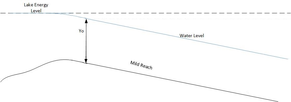
The velocity in a lake is negligible, therefore, the first term of Equation 7 is zero. The energy in a lake equals the depth of water from the lake invert elevation to the elevation of the lake surface. In the below example the energy of the lake is equal to 2.00 feet. The energy at the lake outlet is calculated using the velocity calculated during the iterative process for normal depth, shown in the first iteration in Table 1. This energy is greater than the energy needed to allow the current discharge to pass through the outlet.
An iterative process is used to calculate the normal depth which will meet the energy requirements. Below, Table 1 shows how decreasing the normal depth decreases the discharge, and as a result decreases the energy at the lake outlet. Iterations are performed until a normal depth is found that satisfies the energy balance.
Table 1. Normal depth iterations to balance energy for a slope of 0.004
| Y (ft) | A (ft2) | P (ft) | R (ft) | V (ft/s) | Q (ft3/s) | E (ft) | Fr | Comments |
|---|---|---|---|---|---|---|---|---|
| 1.62 | 16.2 | 13.2 | 1.22 | 5.39 | 87.4 | 2.07 | 0.75 | Reach is mild because Froude number < 1 |
| 1.5 | 15 | 13 | 1.15 | 5.18 | 77.8 | 1.91 | 0.75 | Need to increase depth because E < 2 ft |
| 1.55 | 15.5 | 13.1 | 1.18 | 5.27 | 81.7 | 1.98 | 0.75 | Need to increase depth because E < 2 ft |
| 1.56 | 15.6 | 13.1 | 1.19 | 5.30 | 82.25 | 2.00 | 0.75 | Correct discharge because E = 2 ft |
This iterative process can be used to assess how changing other channel characteristics, such as channel width or roughness, affects the normal depth and energy of the stream.
Relationship between discharge and channel mildness
While the slope of the reach is steep, meaning the Froude number is greater than or equal to one, the discharge of the reach remains the same. Once the reach approaches subcritical conditions, with a Froude number less than one, the discharge gradually decreases. As the reach gets milder, the discharge tends toward zero. Table 2 provides a list of slopes and their corresponding discharges for a rectangular channel of width b equal to 10 feet and Manning's roughness n equal to 0.02. The discharges in this table were calculated using an iterative approach for each of the slopes.
Table 2. Slope and discharge relationship
| Slope (ft/ft) | Discharge (ft3/s) | Froude Number |
|---|---|---|
| 0.01 | 87.4 | 1.18 |
| 0.009 | 87.4 | 1.12 |
| 0.007 | 87.4 | 0.98 |
| 0.0055 | 86.3 | 0.87 |
| 0.004 | 82.25 | 0.75 |
| 0.0025 | 74.4 | 0.59 |
| 0.0017 | 66.0 | 0.49 |
| 0.001 | 54.1 | 0.37 |
| 0.0008 | 49.3 | 0.33 |
| 0.0005 | 40.2 | 0.05 |
| 0.0003 | 31.8 | 0.01 |
| 0.00005 | 13.3 | 0.01 |
| 0 | 0 | 0 |
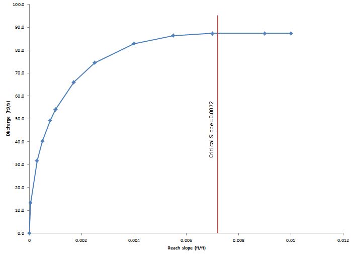
Figure 4 gives a visualization of what happens as slope changes for the given set of channel characteristics. Figure 4 was created using the slopes and corresponding discharges from Table 3. Slopes greater than 0.0072 result in a Froude Number greater than 1. Any slope greater than 0.0072 for these conditions is a steep slope and therefore, has a discharge of 87.4 ft3/s.
Water surface profiles
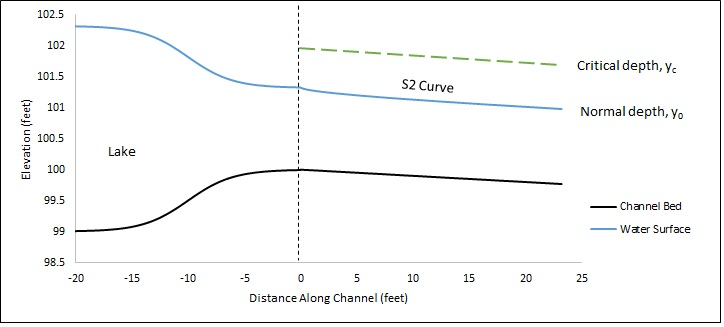
The water surface profile displays how the flow depth changes over a distance between critical depth and normal depth. For a steep reach, the water surface profile downstream of the lake is called an S2 curve. When a lake discharges to a mild reach there is no profile. The flow in the reach is immediately at normal depth. When the lake discharges to a steep reach, there is an S2 profile from the lake outlet to normal depth. As the slope decreases, the S2 curve increases in length. Figure 5 shows the S2 curve for the channel profile given above when Fr=1.18. The standard step method was used for calculating the water surface profiles.
References
- Chanson, H. (1999). The Hydraulics of Open Channel Flow. John Wiley and Sons, Inc..
- Chaudhry, M.H. (2008). Open-Channel Flow. Springer.
- Chow, V.T. (1959). Open Channel Hydraulics. McGraw Hill.
- French, R.H. (1985). Open-Channel Hydraulics. McGraw-Hill Book Co..
- Henderson, F.M. (1966). "Chapter 4: Flow Resistance". Open Channel Flow. The Macmillan Company. pp. 96–115.
- Moglen, G. E. (2013) Lecture notes from CEE 4324/5384: Open Channel Flow, Virginia Tech <https://web.archive.org/web/20121105134341/http://filebox.vt.edu/users/moglen/ocf/index.html>
- Young, Donald (2010). A Brief Introduction to Fluid Mechanics. John Wiley & Sons, Inc..
- http://ocw.mit.edu/courses/earth-atmospheric-and-planetary-sciences/12-090-special-topics-an-introduction-to-fluid-motions-sediment-transport-and-current-generated-sedimentary-structures-fall-2006/lecture-notes/ch5.pdf


