Commodore bus
| 300px | |||
| Type | Peripheral bus | ||
|---|---|---|---|
| Production history | |||
| Designer | Commodore International | ||
| Designed | 1980[1] | ||
| Manufacturer | Various | ||
| Produced | 1980–present | ||
| General specifications | |||
| Length | 1.8 meters maximum[2] | ||
| Hot pluggable | No | ||
| Daisy chain | Yes, up to 31 devices[3] | ||
| External | Yes | ||
| Pins | 6 | ||
| Connector | DIN connector | ||
| Electrical | |||
| Signal | Open collector 5 V | ||
| Max. voltage | 5 V | ||
| Max. current | 3.2 mA[4] | ||
| Data | |||
| Data signal | Yes | ||
| Bitrate | 3.2–41.6 kbit/s[5][6] | ||
| Protocol | Serial | ||
| Pin out | |||
| File:Commodore serial bus DIN socket pinout.png | |||
| Female socket from the front. | |||
| Pin 1 | SRQ | Service Request | |
| Pin 2 | GND | Ground | |
| Pin 3 | ATN | Attention | |
| Pin 4 | CLK | Clock | |
| Pin 5 | DATA | Data | |
| Pin 6 | RESET | Reset | |
The Commodore serial bus (IEC Bus), is Commodore's interface for primarily magnetic disk data storage and printers for Commodore 8-bit home computers: the VIC-20, Commodore 64, Commodore 128, Plus/4,[7] Commodore 16, and Commodore 65.
Description and history
The parallel IEEE-488 interface used on the Commodore PET (1977) computer line was too costly, so a cost reduced version was developed, which consisted of a stripped down, serial version of the IEEE-488 interface, with only a few signals remaining; however, the general protocol layout was kept. Commodore began using this bus with the VIC-20 (1980). Connection to the computer uses a DIN-6 connector (DIN 45322).
Transfer speed
| Setup | Speed | Effective bitrate |
|---|---|---|
| Commodore 64 + 1541 | 400 bytes/s | 3 200 bit/s |
| Commodore 64 + 1541 with fast loader | 2560 bytes/s[5] | 20 480 bit/s |
| Commodore 128 + 1571 | 5200 bytes/s[6] | 41 600 bit/s |
| Theoretical 20 μs[3] | 6250 bytes/s | 50 000 bit/s |
Interface

| Pin | Name | Function |
|---|---|---|
| 1 | /SRQIN | Service request input to let peripherals request to be served by the host (C64). Used by the C128 for fast transfers.[9] |
| 2 | GND | Ground[8] |
| 3 | /ATN | Serial ATN In/out. Set low by the host (C64) to indicate the beginning of a serial data transfer.[9] |
| 4 | /CLK | Serial CLK In/out. Used for software handshaking.[9] |
| 5 | /DATA | Serial DATA In/out. Data bit transfer.[9] |
| 6 | /RESET | Resets peripherals and also resets an older C64.[9] |
Protocol description
The bus signals are digital single-ended open collector 5 volt TTL and active when low. Bus devices have to provide their own power.
Because the bus lines are electrically open collector it works like a long OR gate between all device line drivers. The logical value for ground is true and vice versa. Any device may set a line "true". A line only becomes "false" if all devices signal false.
Transmission begins with the bus talker holding the Clock line true, and the listener(s) holding the Data line true. To begin the talker releases the Clock line to false. When all bus listeners are ready to receive they release the Data line to false. If the talker waits more than 200 μs without the Clock line going true (idle state), listeners have to perform End-or-Identify (EOI).[3]
If the Data line being false (released) isn't acknowledged by the talker within 200 μs, the listener knows that the talker is in the process of EOI that means "this character will be the last one". When the listener detects the 200 μs timeout, it must acknowledge this by pulling the Data line true for at least 60 μs, and then release it. The talker can revert to transmitting again within 60 μs by pulling the Clock line true.[3]
Data is eight bits starting with the least significant bit. The Data line is set according to the bit to send (1=true=ground). Once the Data line is set, the Clock line is released to false. The Clock and Data lines will be held steady for at least 20 μs (except for Commodore 64 that needs 60 μs). After 8 bits has been sent, the talker releases the Data line to false and the listener then acknowledge the talker by pulling the Data line true within 1000 μs. After this the talker sets the Clock line true and listener sets the Data line true thus back where the transmission begun. If an EOI is signaled by holding the Clock line false the transmission is ended and the listener acknowledge this by pulling the Data line true for 200 μs.[3]
The ATN line is set to true and bytes are sent like above to all devices, but the byte is interpreted as one of the commands "Talk," "Listen," "Untalk," and "Unlisten". That tell a specific device to become a talker or listener. Only devices with matching device numbers switch into talk and listen mode. A secondary address may also follow.[3]
On higher logical level the host will set the ATN line to true and transmit the bytes "Device number 8, listen", "Secondary address 2, open". Next it will set the ATN line false and the host then becomes the talker, holding the Clock line true. The device will be the listener, holding the Data line true. The host will transmit the specific open command and end it with an EOI signal sequence. After this the host will set with ATN line true, "Device number 8, unlisten". Followed up by ATN line true and "Device number 8, listen", "Secondary address 2, data". Then the host sets the ATN line false and sends the data. When the host has finished sending data the ATN line is set to true and "Device number 8, unlisten" is sent.[3]
When it is necessary to switch roles and make the host a listener and the device a talker the occurs after a talk command has been sent to the device. The host sets the Data line true and releases the Clock line to false. The device waits for the Clock line to go false and then pulls it to true and release the Data line to false. After this sequence the standard talk-listener interaction may follow.[3]
| Code | Meaning |
|---|---|
| device | 0x20 | Listen, device (0–30) |
| 0x3F | Unlisten, all devices |
| device | 0x40 | Talk, device |
| 0x5F | Untalk, all devices |
| channel | 0x60 | Reopen, channel (0–15) |
| channel | 0xE0 | Close, channel |
| channel | 0xF0 | Open, channel |
To read a normal file from the floppy device number 8 the command LOAD "filename",8,1 is issued on a Commodore 64. That causes the following high level communication to take place:
| Command | Destination | Meaning |
|---|---|---|
| /28 | Device | Listen, device number 8 |
| /F0 | Device | Open channel 0 |
| Device | Send filename bytes | |
| /3F | Devices | Unlisten all devices |
| /48 | Device | Talk, Device number 8 |
| /60 | Device | Reopen channel 0 |
| Device number 8 becomes the master of the bus | ||
| Host | Receive byte data | |
| The host becomes the master of the bus (normal operation) | ||
| /5F | Devices | Untalk all devices |
| /28 | Device | Listen, device number 8 |
| /E0 | Device | Close channel 0 |
| /3F | Devices | Unlisten all devices |
The Commodore 1541 floppy drive uses a slower Commodore 64 compatible mode which can be deactivated for faster speed by using the command OPEN 15,8,15,"UI-":CLOSE 15.[11]
Device numbering
| Device | Type |
|---|---|
| 0 | Keyboard |
| 1 | Cassette port |
| 2 | RS-232 on the user port or second cassette on PETs |
| 3 | Screen |
| 4–5 | Printer |
| 6 | Typically plotter device |
| 7 | Second plotter? |
| 8–15 | Disk (10 – used by some serial-to-parallel printer interfaces) |
| 16–30 | Unknown |
| 31 | Reserved as a command to all devices |
Device number 0–3 are not associated with the Commodore bus.[10]
Host implementation
The VIC-20 computer and the Commodore 1540 and 1541 floppy drives use the MOS Technology 6522 VIA to handle IEC Bus transmissions. The Commodore 64 and 128 computers and the Commodore 1571 drive use the Complex Interface Adapter.
Common devices
| Device | Info |
|---|---|
| Commodore 1541 | 5 1⁄4-inch (130 mm) 170 KB floppy |
| Commodore 1570 | 5 1⁄4-inch (130 mm) 170 KB floppy |
| Commodore 1571 | 5 1⁄4-inch (130 mm) 350–410 KB floppy |
| Commodore 1581 | 3 1⁄2-inch (89 mm) 800 KB floppy |
| MSD SD-1/SD-2 | 5 1⁄4-inch (130 mm) single/dual 170 KB floppy |
| Commodore MPS 801 | Dot-matrix printer |
| Commodore 1515[12] | Dot-matrix printer |
| Commodore 1520 | Ballpoint pen printer |
| Commodore VIC-1525[13] | Dot-matrix printer |
| Commodore VIC-1526 | Rebranded MPS 802, dot-matrix printer |
| Okimate 10 | Dot-matrix printer |
| Commodore DPS-1101[14] | Daisy wheel printer |
| INTERPOD | Standalone IEEE-488 + RS-232[15] |
| VIC-20 | 1 MHz 5 KB computer |
| Commodore 64 | 1 MHz 64 KB computer |
| Commodore SX-64 | 1 MHz 64 KB computer |
| Commodore 128 | 2 MHz 128 KB computer |
| Commodore 16 | 1-2 MHz 16 KB computer |
| Commodore Plus/4 | 1.76 MHz 64 KB computer |
| Commodore 65 | 3.54 MHz 128 KB computer |
Devices
-
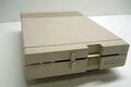
 Commodore 1541 disk drive
 -
 VC 1571 floppy drive
 -
 Commodore 1581 disk drive
 -
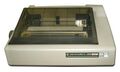 Commodore MPS 802 printer


.jpg)
See also
- Commodore DOS
- Commodore 64 peripherals
- List of device bit rates
- Commodore 1541
- Fast loader
- Magnetic tape data storage
- IEEE-488, the original parallel version (originally HP-IB)
- HP-IL, another serialisation of IEEE-488
References
- ↑ "Commodore VIC-20 History". http://www.commodore.ca/products/vic20/commodore_vic-20.htm.
- ↑ "Building the XE1541 serial cable". https://ist.uwaterloo.ca/~schepers/xe1541.html. "(1) 6' or 1.8 meters (max) 4 conductor shielded cable (for serial connection)"
- ↑ 3.0 3.1 3.2 3.3 3.4 3.5 3.6 3.7 3.8 "How the VIC/64 Serial Bus works". 2015-04-17. https://codebase64.org/doku.php?id=base:how_the_vic_64_serial_bus_works.
- ↑ "6526 complex interface adapter (CIA)". 2016-03-04. http://archive.6502.org/datasheets/mos_6526_cia.pdf. "Output Low Current (Sinking); VOL < .4 v (PA0-PA7, PC, PB0-PB7, DB0-DB7) IOL 3.2 mA"
- ↑ 5.0 5.1 "Design case history: the Commodore 64". 1985. https://spectrum.ieee.org/ns/pdfs/commodore64_mar1985.pdf. "Programming tricks used by Epyx have yielded transfer rates of up to 2.5 kilobytes per second."
- ↑ 6.0 6.1 "Commodore 1571 disk drive specifications". Commodore Business Machines, Inc.. October 1986. ftp://www.zimmers.net/pub/cbm/schematics/drives/new/1571/manual/01.html. (To view documents see Help:FTP)
- ↑ "Using Commodore 1541 disk drive on a Commodore + 4". 2005-10-03. https://plus4world.powweb.com/forum/9314. "The 1541 works with the Plus/4 just fine."
- ↑ 8.0 8.1 "C64 Serial I/O pinout and wiring @ old.pinouts.ru". 2013-12-16. http://old.pinouts.ru/SerialPorts/SerialIOC64_pinout.shtml.
- ↑ 9.0 9.1 9.2 9.3 9.4 "C-64 Workshop / Pin Connections". 2005-12-10. https://ist.uwaterloo.ca/~schepers/MJK/serialbus.html.
- ↑ 10.0 10.1 10.2 "IEC-bus documentation as used for the 1541-III IEC disected". 2008-02-24. https://www.zimmers.net/anonftp/pub/cbm/programming/serial-bus.pdf.
- ↑ "VIC-1541". 2016-03-11. https://www.c64-wiki.com/index.php?title=VIC-1541&oldid=25254.
- ↑ "VIC-1515 User's manual Graphic printer by Commodore". April 1981. http://www.classiccmp.org/cini/pdf/Commodore/VIC-1515%20Printer%20User's%20Manual.pdf.
- ↑ "VIC-1525 Graphics Printer User Manual". Commodore Computer. http://www.classiccmp.org/cini/pdf/Commodore/VIC-1525%20Printer%20User%27s%20Manual.pdf.
- ↑ "Commodore DPS-1101 Daisy Wheel Printer". https://www.recycledgoods.com/commodore-dps-1101-daisy-wheel-printer.html.
- ↑ "Interpod IEEE-488 Interface". April 2008. http://mikenaberezny.com/hardware/c64-128/interpod-ieee-488-interface/.
External links
- "Saving with 64HDD / XE1541 cable length...". 5 July 2003. https://www.lemon64.com/forum/viewtopic.php?t=8348.
- "Design case history: the Commodore 64". IEEE Spectrum. March 1985. https://spectrum.ieee.org/ns/pdfs/commodore64_mar1985.pdf.
- "Serial Bus signal description". https://ist.uwaterloo.ca/~schepers/MJK/serialbus.html.
- "IEC disected". 2008-02-24. https://www.zimmers.net/anonftp/pub/cbm/programming/serial-bus.pdf. – IEC-bus documentation as used for the 1541-III IEC dissected
| General | |
|---|---|
| Standards |
|
| Storage | |
| Peripheral | |
| Audio | |
| Portable | |
| Embedded | |
Interfaces are listed by their speed in the (roughly) ascending order, so the interface at the end of each section should be the fastest. | |
 |  |
