Engineering:Beamwidth

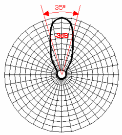
In a radio antenna pattern, the half power beam width is the angle between the half-power (-3 dB) points of the main lobe, when referenced to the peak effective radiated power of the main lobe. See beam diameter. Beamwidth is usually but not always expressed in degrees and for the horizontal plane.
The beamwidth can be computed for arbitrary antenna arrays. Defining the array manifold as the complex response of the element antenna array as , where is a matrix with rows, the beam pattern is first computed as:
where is the conjugate transpose of at the reference angle .
From the beam pattern , the antenna power is computed as:
The half power beamwidth (HPBW) is then found as the range of where .
Note that other definitions of beamwidth exist, such as the distance between nulls and distance between first side lobes.
Sources
- Van Trees, H. L. (2002). Optimum Array Processing. New York: Wiley.
- E. Tuncer and B. Friedlander (Editors), "Classical and Modern Direction-of-Arrival Estimation", Academic Press, 2009.
See also
