Engineering:Components of jet engines
}}

This article describes the components and systems found in jet engines. It uses two example engines; the type most familiar to the general public, the modern airliner engine, and the military afterburning engine. The components and systems make up what is known as a bare engine.[1]
The article also has a section on inlets. Although the inlet is not part of the engine, the engine relies on it to help prevent compressor surging (by reducing inlet distortion), and to give a pressure boost to the engine which reduces its fuel consumption (by converting the relative speed of the approaching air into pressure).
The article also mentions the nacelle because the outside of an airliner engine has to be streamlined so that as little of its thrust as possible is lost to the drag of the air flowing past the engine.
Overview of components in a modern airliner engine


Engines for airliners are enclosed in a streamlined pod called a nacelle which hangs under the wing or, on smaller aircraft, on the side of the aircraft behind the wing.
The most fundamental part of the engine is the gas generator ( also known as the core) because every gas turbine engine needs one (it has 3 parts, compressor, combustion chamber and turbine).[2] Early jet engines (turbojets) were just a gas generator until additional parts were added to reduce fuel consumption. In front was added a fan and, at the back, another turbine, both connected together by a shaft going through the middle of the gas generator, (and known as a fanjet, bypass engine, or turbofan).
For an airline passenger the gas generator is out-of-sight in the middle of the engine and all that can be seen of the engine itself are the fan at the front and the turbine for the fan at the back inside the core nozzle.
Major components

The major components of an airliner engine are shown on the 'Schematic of a high bypass turbofan'. The engine is identified as 2-spool. Spool is a name given to a complete rotor consisting of compressor, turbine and connecting shaft.[3]
- Intake- A short length of ducting in front of the fan is not part of the engine ( it comes with the nacelle) but is required by the fan to make sure the air approaching it is reasonably smooth (not too much distortion). A rounded lip at the entry to the intake ensures this.
- Fan- The first part of the engine is the fan. It is a compressor and raises the pressure of the air which flows into the engine by a small amount (about 1/2 an atmosphere). Most of the air passing through the fan leaves the engine at the fan nozzle. A smaller amount goes into the LP compressor and then the gas generator ( which consists of HP compressor, combustion chamber and HP turbine).


- Fan nozzle- Is the area required to back-pressure the fan to make it run properly as a compressor.[4] At the same time the nozzle accelerates the fan airflow as it leaves the bypass duct.[5][6]
- LP compressor- The air that passes through the fan close to the fan hub (with a small pressure rise) passes through the LP compressor with a further rise in pressure. This air is known as the core air and gives a pressure boost to the gas generator.
- Gas generator- In between the fan and its turbine is a gas generator where the fuel is burned and its energy transferred to the air passing through the combustion chamber. The gas generator consists of an HP compressor, a combustion chamber (fuel is burned continuously after initially being ignited during the engine start) and an HP turbine. The compressor is needed because fuel has to be burned in high pressure air to get the most energy out of it[7] (the LP booster has already helped this). The turbine is needed to drive the compressor.
- LP turbine- This is the turbine which drives the fan and LP compressor. It can be seen looking in the back of the engine.
- Core nozzle- Is the area required to back-pressure the gas generator compressor to make it run properly as a compressor.[8] It also accelerates the core flow as it leaves the engine.[9]
- Nacelle- The streamlined pod around the engine. It also incorporates a fan-air thrust reverser which has blocker doors and a set of turning vanes to direct the air forwards to help slow the aircraft on landing.
Two significant extra components are also used on modern airliner engines compared to the 2-spool arrangement shown above.
- Fan Drive Gear System- The FDGS is a planetary reduction gearbox. The power from the LP turbine goes through the gears and the fan turns at only 1/3 the turbine speed, when used on the Pratt & Whitney PW1000G. This type of engine is known as a geared turbofan. The 2-spool engine as described above is known as a direct drive turbofan.
- Intermediate Pressure spool- A third spool, known as the IP spool, is used on the Rolls-Royce Trent.
Overview of components in a modern supersonic engine

Most of the same components are needed but some differ noticeably in appearance, as does the bare engine itself. The fan is much smaller and has more than one set of blades, for example. There is no thrust reverser but there is an afterburner. One or two engines are installed in the body of the aircraft behind the cockpit.

- Intake- Compared to the airliner intake, the one on a combat aircraft is a curved passage because the engine located behind the cockpit is offset from the entrance to the inlet. The relatively slow-moving air on the aircraft skin (boundary layer) has to be prevented from entering the intake. The air approaching the intake at supersonic speed has to be slowed to subsonic speed at the entrance, keeping as much of its energy as possible as a rise in pressure for the engine.
- Fan- The fan is much smaller because less air goes past the core than through it (For the airliner engine more than eight times as much bypasses the core). When much less bypass air is needed the engine gives its best performance if the bypass air is compressed more, so 3 stages are needed (only one on an airliner engine).

- Afterburner- The cold fan air and the hot LP turbine exhaust come together in the afterburner. When the afterburner is selected fuel is sprayed in and ignited with igniters (the turbine exhaust is not hot enough to do this). The flame is held in position in the flowing gas using flame holders which can be seen by looking into the afterburner.
- Nozzle- The nozzle has an adjustable area which is increased when fuel is being burned in the afterburner (more fuel, bigger area). Increasing the area in proportion with the burning keeps the engine operating the same as when the afterburner is not lit (because the airflow through the engine hasn't changed).
How the components and systems work
Compressors

_MTU-Museum_20231112_04w.jpg)


The job of the compressor is to raise the pressure of ambient air as high as possible with the level of technology existing at the time (the higher the pressure the greater the proportion of energy in the fuel that is transferred to the air in the combustor, which means less wasted fuel).[10] For the illustrated J79 engine it was 12 atmospheres (General Electric compressor knowledge in 1952).
The air is squeezed by very fast moving blades in a close-fitting tube. The exit from the tube is smaller than the entry as the squeezed air (higher density/smaller volume) takes up less space. The high pressure is attained at high speed and the small exit area is only correct for the high-speed density (small volume). At low engine speeds the slower moving blades don't compress the air so much and the exit area is too small to pass the low-speed (bigger) volume. This affects the angle the blades meet the their approaching air (see following explanation).
The speed of the air moving through the compressor and the speed of the blades combine to give the blade angle of attack (explained using velocity triangles[11]) and if too much, similar to an aircraft wing, the compressor air flow stalls. This condition happens at low compressor speeds and stops the compressor getting to its high-speed/works-well condition. Three additions to a compressor enable it to run without blade stall at low speeds (see following).
The J79 illustration shows the use of variable angle blades in the first half of the compressor. The J57 illustration shows a (combined 12 atmosphere) compressor split into two separately-spinning compressors, both of which work well because, individually, they only compress their own bit of airflow 3 or 4 times (3x4=12). The Avon illustration shows where air escapes at low engine speeds (three bleed valves).
These examples are all early jet engines. More recent engines use all three solutions together, as illustrated here on a model of the V2500 airliner engine
.
Combustors
Why is a combustor required?
The volume of air determines the amount of work which has to be put into compressing or which can be got out during expansion. So more work can be obtained after heating compressed air (due to the increased volume of the working fluid) by expanding it (in a turbine) than was needed to compress it. The combustor heats the air and with the turbine driving the compressor there is a surplus available to form a propelling jet (or drive an additional turbine).[14]


The air leaving the compressor has to be slowed for combustion
Slowing the air reduces the pressure loss in the combustor (less pressure loss, lower fuel consumption). Also, less pressure loss means combustion takes place at a higher pressure which increases combustion efficiency (lower fuel consumption).[15] The air leaving the compressor is initially slowed when it enters a bigger annulus (see accompanying image of Adour engine). Air going into the combustor with the fuel spray is still going too fast for a flame to exist. The flame front doesn't move fast enough to remain inside the combustor against the incoming air flow. A sheltered combustion zone with a reverse flow region has to be established (using air swirl around the fuel spray and holes in the combustor wall). This enables the flame to remain in a stable location (primary zone) near the fuel nozzles and is a continuous ignition source for incoming air and fuel.[16]
Cooling the combustor
After the air required for combustion has entered the front of the combustor further air enters through many holes in the wall of the combustor to provide wall-cooling with a film of cooler air to insulate the metal surfaces which have a protective thermal barrier.[17]
Cooling the combustion gasses for the turbine
Since the turbine cannot withstand the stoichiometric temperatures (a mixture ratio of around 15:1) in the combustion zone, the compressor air remaining after supplying the primary zone and wall-cooling film, and known as dilution air, is used to reduce the gas temperature at entry to the turbine to an acceptable level (an overall mixture ratio of between 45:1 and 130:1 is used[18]).
Turbines
_MTU-Museum_20231112_08w.jpg)
Because a turbine expands from high to low pressure, there is no such thing as turbine surge or stall. The turbine needs fewer stages than the compressor. The blades have more curvature and the gas stream velocities are higher.
Designers must, however, prevent the turbine blades and vanes from melting in a very high temperature and stress environment. Consequently, bleed air extracted from the compression system is often used to cool the turbine blades/vanes internally. Other solutions are improved materials and/or special insulating coatings. The discs must be specially shaped to withstand the high stresses imposed by the rotating blades. Improved materials help to keep disc weight down.
Cooling systems
All jet engines require high temperature gas for good efficiency, typically achieved by combusting hydrocarbon or hydrogen fuel. Combustion temperatures can be as high as 3500K (5841F) in rockets, far above the melting point of most materials, but normal airbreathing jet engines use rather lower temperatures.
Cooling systems are employed to keep the temperature of the solid parts below the failure temperature.
Air systems
Gas turbines have a secondary air system which is fundamental to the operation of the engine. It provides cooling air to the turbines, airflow into bearing cavities to prevent oil flowing out and cavity pressurization to ensure rotor thrust loads give acceptable thrust bearing life.
Air, bled from the compressor exit, passes around the combustor and is injected into the rim of the rotating turbine disc. The cooling air then passes through complex passages within the turbine blades. After removing heat from the blade material, the air (now fairly hot) is vented, via cooling holes, into the main gas stream. Cooling air for the turbine vanes undergoes a similar process.
Cooling the leading edge of the blade can be difficult, because the pressure of the cooling air just inside the cooling hole may not be much different from that of the oncoming gas stream. One solution is to incorporate a cover plate on the disc. This acts as a centrifugal compressor to pressurize the cooling air before it enters the blade. Another solution is to use an ultra-efficient turbine rim seal to pressurize the area where the cooling air passes across to the rotating disc.
Seals are used to prevent oil leakage, control air for cooling and prevent stray air flows into turbine cavities.
A series of (e.g. labyrinth) seals allow a small flow of bleed air to wash the turbine disc to extract heat and, at the same time, pressurize the turbine rim seal, to prevent hot gases entering the inner part of the engine. Other types of seals are hydraulic, brush, carbon etc.
Small quantities of compressor bleed air are also used to cool the shaft, turbine shrouds, etc. Some air is also used to keep the temperature of the combustion chamber walls below critical. This is done using primary and secondary airholes which allow a thin layer of air to cover the inner walls of the chamber preventing excessive heating.
Exit temperature is dependent on the turbine upper temperature limit depending on the material. Reducing the temperature will also prevent thermal fatigue and hence failure. Accessories may also need their own cooling systems using air from the compressor or outside air.
Air from compressor stages is also used for heating of the fan, airframe anti-icing and for cabin heat. Which stage is bled from depends on the atmospheric conditions at that altitude.
Control system
Jet engines are controlled using Full Authority Digital Electronics Control systems. Engine thrust has to be maintained or varied at the will of the pilot by varying the fuel flow. But it has to be done without exceeding any limitations which could damage the engine or cause a flame-out (a combustible mixture has to be maintained in the combustion chambers to prevent lean or rich flame-out). Complex hydromechanical units were used to implement these requirements before electronic engine controls were developed.
Ignition
Usually there are two igniter plugs in different positions in the combustion system. A high voltage spark is used to ignite the gases. The voltage is stored up from a low voltage (usually 28 V DC) supply provided by the aircraft batteries. It builds up to the right value in the ignition exciters (similar to automotive ignition coils) and is then released as a high energy spark. Depending on various conditions, such as flying through heavy rainfall, the igniter continues to provide sparks to prevent combustion from failing if the flame inside goes out. Of course, in the event that the flame does go out, there must be provision to relight. There is a limit of altitude and air speed at which an engine can obtain a satisfactory relight.
For example, the General Electric F404-400 uses one igniter for the combustor and one for the afterburner; the ignition system for the A/B incorporates an ultraviolet flame sensor to de-activate the igniter after light-off on minimum fuel has been detected.
Most modern ignition systems provide enough energy (20–40 kV) to be a lethal hazard should a person be in contact with the electrical lead when the system is activated, so team communication is vital when working on these systems.
Oil system
.jpg)

.jpg)
_Boeing_737-838_(WL)_at_the_Canberra_Airport_open_day_(6).jpg)
Oil is used to lubricate and cool bearings and gears, to cool the inside surfaces of hot bearing compartments and to keep the system clean by passing the oil through filters. It is also used as the squeeze-film in the main bearings.[21]
Oil is lost from the system as a mist from the overboard vent (breather), and as drips from leaking seals on accessory drive shafts.
Functions of the system
Source:[22]
- Storage- in the oil tank,
- Distribution- supplies pressurized oil to bearings and gears, removing heat and debris, filters debris and cools the oil using fuel and bypass air,
- Scavenge- removes oil from bearing compartments and returns to tank,
- Venting- removes air and oil mist from bearing compartments, separates oil to the tank, and air overboard through a breather,
- Indicating- quantity of oil in the tank, oil pressure, oil temperature, presence of particles on chip detectors, debris in filter showing as a developing blockage.
Route taken by oil
Oil starts its journey at the oil tank. A (pressure) pump forces the oil through all the tubes going to the bearings and gears. It shoots out of small holes (jets) pointing at them in their sealed enclosures (chambers or sumps). The oil lubricates and cools them and becomes hot in turn. It also finds its way into the small gap around the outside of the bearing where it gets squeezed when the bearing tries to move radially. This oil film reduces (damps) the severity with which the supported shaft (with any out-of-balance) shakes the engine.
Oil mist swirling around the bearing 'sees' very narrow escape paths round the shaft where it comes through the sump walls, but it's mostly held back by inrushing (sealing) air.
The oil drains from the sump and passes by a magnet (the chip detector) which attracts any magnetic debris. It is pumped along, together with the air which sealed it in the sump, by (scavenge) pumps, then through a filter which traps any debris that may be present.
The hot oil is cooled by passing it through tubes with cold fuel on the other side (fuel/oil heat exchanger). If the oil is still too hot it passes through tubes with cold air on the other side (air/oil heat exchanger) in the bypass duct.
The sealing air has to be discarded, but with as little oil mist as possible. Most of the oil is spun out of the air (centrifuged) and goes back in the tank. The air escapes from the engine through a vent (breather). Oil that escapes from the breather is a contributor to the engine oil consumption.[23]
Breather vents are located on the gearbox on Rolls-Royce and Pratt & Whitney engines. Breather air uses the hollow fan shaft on CFM engines.[24] It passes through a flame arrestor before leaving the engine at the tip of the exhaust cone.
Oil leaks from accessory drive shaft seals are another contributor to oil consumption. An example maximum allowed is 3 drops per minute from carbon seals.
Power take-off sump
One of the bearing sumps also includes the gears (so sometimes called the internal gearbox) which take power from the spool for driving an accessory gearbox on the outside of the engine.
The power take-off for the accessory drive is a bevel gear specifically located next to the shaft thrust (ball) bearing to minimize unwanted movement relative to its mating radial driveshaft bevel gear.[26]
This sump may include the thrust bearings for all shafts as well as the radial accessory drive. For example, 3 ball bearings on the 3-shaft Rolls-Royce Trent engine which uses the IP shaft for the external gearbox, and 2 ball bearings on the 2-shaft CFM International LEAP engine with accessory drive from the HP shaft.
Air intakes
The air intake (inlet U.S.[27]) is an aerodynamic duct extending from an entry lip to the engine fan/compressor. For supersonic intakes with variable geometry it is called an intake system, referring to the need for shock-wave and internal duct flow management using variable position surfaces (ramps or cones) and bypass doors.[28] The duct may be part of the fuselage structure with entry lip in various locations (aircraft nose - Corsair A-7, fuselage side - Dassault Mirage III), or located in an engine nacelle attached to the fuselage (Grumman F-14 Tomcat, Bombardier CRJ) or wing (Boeing 737).
Subsonic inlets

Pitot inlets are used for subsonic aircraft. A pitot inlet is little more than a tube with an aerodynamic fairing around it.
When an aircraft is not moving, and there is no wind, air approaches the intake from all directions: directly ahead, from the side, and from behind.
At low airspeeds, the streamtube approaching the lip is larger in cross-section than the lip flow area, whereas at the intake design flight Mach number the two flow areas are equal. At high flight speeds the streamtube is smaller, with excess air spilling round the lip.
Radiusing of the lip prevents flow separation and compressor inlet distortion at low speeds during crosswind operation and take-off rotation.

Supersonic inlets
Supersonic intakes exploit shock waves to decelerate the airflow to a subsonic condition at compressor entry.
There are basically two forms of shock waves:
- Normal shock waves lie perpendicular to the direction of the flow. Normal shock waves tend to cause a large drop in stagnation pressure. The higher the supersonic entry Mach number to a normal shock wave, the lower the subsonic exit Mach number and the stronger the shock (i.e. the greater the loss in stagnation pressure across the shock wave).
- Conical (3-dimensional) and oblique shock waves (2D) are angled rearwards, like the bow wave on a ship or boat, and radiate from a flow disturbance such as a cone or a ramp. For a given inlet Mach number, they are weaker than the equivalent normal shock wave and, although the flow slows down, it remains supersonic throughout. Conical and oblique shock waves turn the flow, which continues in the new direction, until another flow disturbance is encountered downstream. Note: Comments made regarding 3 dimensional conical shock waves, generally also apply to 2D oblique shock waves.
A sharp-lipped version of the pitot intake, described above for subsonic applications, performs quite well at moderate supersonic flight speeds. A detached normal shock wave forms just ahead of the intake lip and 'shocks' the flow down to a subsonic velocity. However, as flight speed increases to higher Mach numbers, the shock wave becomes stronger, causing a larger percentage decrease in stagnation pressure (i.e. poorer pressure recovery). An early US supersonic fighter, the F-100 Super Sabre, used such an intake. They are also found on more modern combat aircraft designs such as the F-16 Fighting Falcon and the F/A-18 Hornet that operate primarily operate at subsonic and transonic speeds with transient supersonic dashes, and are thus chosen for their light weight and simplicity due to their fixed geometry.

More advanced supersonic intakes, excluding pitots:
a) exploit a combination of conical shock wave/s and a normal shock wave to improve pressure recovery at high supersonic flight speeds. Conical shock wave/s are used to reduce the supersonic Mach number at entry to the normal shock wave, thereby reducing the resultant overall shock losses.
b) have a design shock-on-lip flight Mach number, where the conical/oblique shock wave/s intercept the cowl lip, thus enabling the streamtube capture area to equal the intake lip area. However, below the shock-on-lip flight Mach number, the shock wave angle/s are less oblique, causing the streamline approaching the lip to be deflected by the presence of the cone/ramp. Consequently, the intake capture area is less than the intake lip area, which reduces the intake airflow. Depending on the airflow characteristics of the engine, it may be desirable to lower the ramp angle or move the cone rearwards to refocus the shockwaves onto the cowl lip to maximise intake airflow.
c) are designed to have a normal shock in the ducting downstream of intake lip, so that the flow at compressor/fan entry is always subsonic. This intake is known as a mixed-compression inlet. However, two difficulties arise for these intakes: one occurs during engine throttling while the other occurs when the aircraft speed (or Mach) changes. If the engine is throttled back, there is a reduction in the corrected (or non-dimensional) airflow of the LP compressor/fan, but (at supersonic conditions) the corrected airflow at the intake lip remains constant, because it is determined by the flight Mach number and intake incidence/yaw. This discontinuity is overcome by the normal shock moving to a lower cross-sectional area in the ducting, to decrease the Mach number at entry to the shockwave. This weakens the shockwave, improving the overall intake pressure recovery. So, the absolute airflow stays constant, whilst the corrected airflow at compressor entry falls (because of a higher entry pressure). Excess intake airflow may also be dumped overboard or into the exhaust system, to prevent the conical/oblique shock waves being disturbed by the normal shock being forced too far forward by engine throttling.
The second difficulty occurs when the aircraft Mach number changes. The airflow has to be the same at the intake lip, at the throat and at the engine. This statement is a consequence the conservation of mass. However, the airflow is not generally the same when the aircraft's supersonic speed changes. This difficulty is known as the airflow matching problem which is solved by more complicated inlet designs than are typical of subsonic inlets. For example, to match airflow, a supersonic inlet throat can be made variable and some air can be bypassed around the engine and then pumped as secondary air by an ejector nozzle.[29] If the inlet flow is not match, it may become unstable with the normal shock wave in the throat suddenly moving forward beyond the lip, known as inlet unstart.[30] Spillage drag is high and pressure recovery low with only a plane shock wave in place of the normal set of oblique shock waves. In the SR-71 installation the engine would continue to run although afterburner blowout sometimes occurred.[31]
Ferri scoop
A Ferri-type intake, which used a prominent, swept-forward lip, a configuration also used for the wing-root inlets.[32] Notable aircraft that used this example was the Republic AP-75, XF-103, F-105, XF8U-3, and SSM-N-9 Regulus II cruise missile.[33]
Inlet cone
Many second generation supersonic fighter aircraft featured an inlet cone, which was used to form the conical shock wave. This type of inlet cone is clearly seen at the very front of the English Electric Lightning and MiG-21 aircraft, for example.
The same approach can be used for air intakes mounted at the side of the fuselage, where a half cone serves the same purpose with a semicircular air intake, as seen on the F-104 Starfighter and BAC TSR-2.
Some intakes are biconic; that is they feature two conical surfaces: the first cone is supplemented by a second, less oblique, conical surface, which generates an extra conical shockwave, radiating from the junction between the two cones. A biconic intake is usually more efficient than the equivalent conical intake, because the entry Mach number to the normal shock is reduced by the presence of the second conical shock wave.
The intake on the SR-71 had a translating conical spike which controlled the shock wave positions to give maximum pressure recovery.[34]
Inlet ramp
For rectangular intakes the equivalent way to generate the required shock system, compared to circular intake conical bodies, is to use ramps. A ramp causes an abrupt airflow deviation in supersonic flow as does the presence of a conical surface.
Two vertical ramps were used in the F-4 Phantom intake, the first with a fixed wedge angle of 10 degrees and the second with a variable additional deflection above Mach 1.2.[35] Horizontal ramps were used in the Concorde intakes. Some designs have variable capture area, such as on the F-15 Eagle.
More modern "caret" style inlets, such as on the F-22 Raptor, have fixed ramps and cowls that are swept in multiple axes to generate oblique shocks, with shock positions adjusted using downstream pressure. The fixed-geometry improves the aircraft's stealth characteristics and survivability.
-
 F-4 Phantom showing fixed front ramp, ref "702", and moveable rear ramp
 -
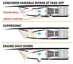 Concorde intake operating modes showing position of horizontal "moveable ramps"


Diverterless supersonic inlet
A further evolution and optimization of the Ferri scoop, the diverterless supersonic inlet (DSI) consists of a "bump" and a forward-swept inlet cowl, which work together to divert boundary layer airflow away from the aircraft's engine while generating a 3D shock structure to compress the air and slow it down from supersonic speed. This enables the elimination of bleed and bypass systems, thus saving weight and cost. The DSI can be used to replace conventional methods of controlling supersonic and boundary layer airflow.
At speeds up to Mach 2, the DSI achieves relatively decent pressure recovery performance and can be used to replace the intake ramp and inlet cone, which are more complex, heavy and expensive. The first production application of the DSI is on the F-35 Lightning II[36]
Blow-in doors
-
 Blow-in doors on an TAV-8A Harrier
 -
 P&W JT3D engine nacelles with blow-in doors on a Boeing 707
.jpg)

Blow-in doors (or suck-in doors) are spring-loaded panels on early jet engine air intakes (like on Boeing 707s[37], early 737s, and Harriers) that open at low speeds and high thrust (takeoff/landing) to provide extra airflow, preventing engine stalls and reducing intake noise, a compromise not found on modern engines as designs evolved. They function by negative pressure, essentially "blowing" air in when the engine demands more than available airspeed can provide, then closing as speed increases.[38]
See also
- Index of aviation articles
- Advanced Technology Engine
Notes
- ↑ Note the big difference in size of the core compared to the front of the engine (because 8 times as much air flows past the core compared to how much flows through it)
- ↑
A. Fan and its turbine (turquoise)
B. Gas generator (yellow) produces high energy gas to drive fan and give small amount of thrust
C. Nacelle (green) includes inlet, bypass duct, thrust reverser (not shown)
1. Air intake for gas generator and bypass air
2. Fan
3. Boost compressor for gas generator
4/5/6. Gas generator components: compressor/combustor/turbine
7. Turbine for fan and boost compressor
8. Gas generator exhaust
9. Bypass air exit - ↑ This model shows the fan, 4-stage LP compressor, gas generator with 10-stage HP compressor, combustion chamber and 2-stage HP turbine, 5-stage fan/LP compressor turbine
- ↑ A passenger's view showing where fan air comes out of the side of the engine, after having its normal path blocked. It comes through the black grille, where it is turned forwards. The aircraft is moving to the left.
- ↑ Note the diameter of the engine is barely noticeably bigger than the front because only half as much air bypasses the core
- ↑ Note the inlet is offset from the engine with duct curving up to the engine fan.
- ↑ Note the radial flameholders. They have to be cooled with air flowing radially inwards from the bypass duct.
- ↑ Air moves from left to right. Each compressor stage is a row of rotor blades which give the air tangential velocity followed by a stationary row of stator blades which slow the air and raise its static pressure. The top casing holding the stators has been removed to show the rotor blades. Visible on the bottom casing are the actuating levers for the six stages of variable stators. The blades and air passage get smaller from left to right because the volume of each pound of air gets smaller as the air is compressed from 1 atmosphere to 12.
- ↑ The combustor fits in a casing which has to resist the pressure of the air leaving the compressor, the highest gas pressure in the engine. The outside is ambient pressure so the casing is subjected to the overall pressure ratio of the engine.
- ↑ The air slowing as it enters the combustion case is visually apparent by comparing the height of the compressor exit vane and the widened passage in the combustor casing (it has been diffused by the increase in flow area)
- ↑ Each stage is a stationary ring of nozzle guide vanes followed by spinning blades. The gas is moving from left to right and the 2nd and 3rd vane rings have been removed to better show the blades. The first ring shows the shape of the vanes and how they turn the gas from the combustor into a tangential direction necessary to spin the bladed disc.
References
- ↑ Systems of Commercial Turbofan Engines, An Introduction to Systems Functions, Andreas Linke-Diesinger, ISBN 978-3-540-73618-9, Section 10-2
- ↑ JET PROPULSION A Simple Guide to the Aerodynamic and Thermodynamic Design and Performance of Jet Engines,Nicholas Cumpsty 2003,ISBN 978 0 521 54144 2, Fig.4.1
- ↑ https://www.geaerospace.com/sites/default/files/t901-what-is-a-spool.pdf [bare URL PDF]
- ↑ JET PROPULSION A Simple Guide to the Aerodynamic and Thermodynamic Design and Performance of Jet Engines,Nicholas Cumpsty 2003,ISBN 978 0 521 54144 2,p.120
- ↑ JET PROPULSION A Simple Guide to the Aerodynamic and Thermodynamic Design and Performance of Jet Engines,Nicholas Cumpsty 2003,ISBN 978 0 521 54144 2,xii
- ↑ The Aerothermodynamics Of Aircraft Gas Turbine Engines, Oates, Air Force Aero Propulsion Laboratory, Wright-Patterson AFB, https://apps.dtic.mil/sti/citations/ADA059784, page 26-19
- ↑ On the thermodynamic spectrum of airbreathing propulsion,Carl Builder,Published Online:16 Aug 2012https://doi.org/10.2514/6.1964-243,p.2
- ↑ JET PROPULSION A Simple Guide to the Aerodynamic and Thermodynamic Design and Performance of Jet Engines,Nicholas Cumpsty 2003,ISBN 978 0 521 54144 2,p.164
- ↑ The Aerothermodynamics Of Aircraft Gas Turbine Engines, Oates, Air Force Aero Propulsion Laboratory, Wright-Patterson AFB, https://apps.dtic.mil/sti/citations/ADA059784, page 26-19
- ↑ On the thermodynamic spectrum of airbreathing propulsion,Carl Builder,Published Online:16 Aug 2012https://doi.org/10.2514/6.1964-243,p.2
- ↑ Ideas and Methods of Turbomachinery Aerodynamics: A Historical View,Cumpsty et al.,p.16, https://arc.aiaa.org/doi/abs/10.2514/1.9176?journalCode=jpp
- ↑ Powering the World's Airliners: Engine Developments from the Propeller to the Jet Age, Decher,ISBN 978-1526759146,pp.143-146
- ↑ Flow Matching Of The Stages Of Axial Compressors, Wilde, Technical Series No.4,ISBN 1 872 922 14 7,pp.53 and 67
- ↑ Gas Turbines And Their Problems, Hayne Constant 1948, Todd Reference Library, Todd Publishing Group Ltd., London W.1, p.11
- ↑ On the thermodynamic spectrum of airbreathing propulsion,Carl Builder,Published Online:16 Aug 2012https://doi.org/10.2514/6.1964-243,p.2
- ↑ GAS TURBINE COMBUSTION—Alternative Fuels and Emissions, Lefebvre and Ballal, ISBN 978-1-4200-8605-8, https://www.ebooks.com/en-ca/book/533775/gas-turbine-combustion/arthur-h-lefebvre/?_c=1, FIGURE 1-16
- ↑ Gas Turbine Combustion Third Edition, Lefebvre and Ballal,ISBN 978 1 4200 8605 8, pp.8,15,17
- ↑ The Combustion Chamber
- ↑ https://www.scribd.com/presentation/877797332/Cfm56-7b-Familiarization-Print-pp
- ↑ Leaking oil seals contribute to the engine oil consumption.
- ↑ The Jet Engine,Rolls-Royce 1986, Fifth edition,ISBN 0 902121 235,p.81
- ↑ Systems of Commercial Turbofan Engines,An Introduction to Systems Functions,Andreas Linke-Diesinger,ISBN 978-3-540-73618-9, pp.51/52
- ↑ Exxon Jet Engine oil System:Part1. 'Typical jet engine oil system' https://www.exxonmobil.com/en/aviation/knowledge-library/resources/jet-engine-oil-system-1
- ↑ Systems of Commercial Turbofan Engines,An Introduction to Systems Functions,Andreas Linke-Diesinger,ISBN 978-3-540-73618-9, p.59
- ↑ TRENDS OF ROLLING-CONTACT BEARINGS AS APPLIED TO AIRCRAFT GAS-TURBINE ENGINES,NACA TN 3110, App.A,Fig.8,https://digital.library.unt.edu/ark:/67531/metadc57005/m1/4/
- ↑ The Jet Engine,Rolls-Royce 1986, Fifth edition,ISBN 0 902121 235,p.67
- ↑ Intake Aerodynamics Second Edition, Seddon Goldsmith 1999,ISBN 0 632 04963 4, p.xi
- ↑ B-70 Aircraft Study Final Report Volume IV, April 1972, Taube, SD 72-SH-0003, Space Division North Ameriacan Rockwell, p.iii
- ↑ enginehistory.org "How supersonic inlets work" J. Thomas Anderson Fig1
- ↑ enginehistory.org "How supersonic inlets work" J. Thomas Anderson Section 5.2 "Inlet operating map"
- ↑ "SR-71 Revealed The Inside Story" Richard H. Graham, Col USAF (Ret) ISBN 978-0-7603-0122-7 p56
- ↑ https://ntrs.nasa.gov/api/citations/19930087347/downloads/19930087347.pdf [bare URL PDF]
- ↑ "Scoop-type supersonic inlet with precompression surface". https://patents.google.com/patent/US2990142A/en.
- ↑ enginehistory.org "How supersonic inlets work" J. Thomas Anderson Section 4.3 "Spike translation"
- ↑ Propulsion System Installation Corrections, Volume III Sample Cases, Ball, Air Force Flight Dynamics Laboratory AFFDL-TR-72-147, p.37 F-4J inlet
- ↑ Hehs, Eric (15 July 2000). "JSF Diverterless Supersonic Inlet". Code One magazine. Lockheed Martin. http://www.codeonemagazine.com/article.html?item_id=58.
- ↑ Aircraft Noise Abatement, Hearings Before the Subcommittee, United States. Congress. House. Science and Astronautics Committee (1974), Page 133
- ↑ Mach 1 and Beyond: The Illustrated Guide to High-Speed, Lawrence W. Reithmaier (1995), Page 101
 |  |
