Engineering:Jet engine performance
A jet engine converts fuel into thrust. One key metric of performance is the thermal efficiency; how much of the chemical energy (fuel) is turned into useful work (thrust propelling the aircraft at high speeds). Like a lot of heat engines, jet engines tend to not be particularly efficient (<50%); a lot of the fuel is "wasted". In the 1970s, economic pressure due to the rising cost of fuel resulted in increased emphasis on efficiency improvements for commercial airliners.
Jet engine performance has been phrased as 'the end product that a jet engine company sells'[1] and, as such, criteria include thrust, (specific) fuel consumption, time between overhauls, power-to-weight ratio. Some major factors affecting efficiency include the engine's overall pressure ratio, its bypass ratio and the turbine inlet temperature.
The following parameters that indicate how the engine is performing are displayed in the cockpit: engine pressure ratio (EPR), exhaust gas temperature (EGT) and fan speed (N1). EPR and N1 are indicators for thrust, whereas EGT is vital for gauging the health of the engine,[2] as it rises progressively with engine use over thousands of hours, as parts wear, until the engine has to be overhauled.
The performance of an engine can calculated using thermodynamic analysis of the engine cycle. It calculates what would take place inside the engine. This, together with the fuel used and thrust produced, can be shown in a convenient tabular form summarising the analysis.[3]
Introduction
An introductory look at jet engine performance may be had in a cursory but intuitive way with the aid of diagrams and photographs which show features that influence the performance. An example of a diagram is the velocity triangle which in everyday life tells cyclists why they struggle against wind from certain quarters (and where head-on is worst) and in the engine context shows the angle air is approaching compressor blades (head-on is best for low losses). The use of velocity triangles in compressors and turbines to show the all-important angle at which air approaches the blading goes back to early steam turbines.[4]
Photographs show performance-enhancing features such as the existence of bypass airflow (increased propulsive efficiency) only visually obvious on engines with a separate exit nozzle for the bypass air. They are also used to show rarely seen internal details such as honeycomb seals which reduce leakage and save fuel (increased thermal efficiency), and degrading details such as the rub marks on centrifugal impeller blades which indicate loss of material, increased air leakage and fuel consumption.
Jet engines perform in two basic ways, the combined effect of which determines how much waste they produce as a byproduct of burning fuel to do thrust work on an aircraft.[5] First is an energy conversion as burning fuel speeds up the air passing through which at the same time produces waste heat from component losses (thermal efficiency). Second, part of the power which has been given to the air by the engine is transferred to the aircraft as thrust work with the remaining part being kinetic energy waste in the wake (propulsive efficiency). The two efficiencies were first formulated in the 19th century for the steam engine (thermal efficiency ) and the ship's propeller (propulsive or Froude efficiency ).
A visual introduction to jet engine performance, from the fuel efficiency point of view, is the Temperature~entropy (T~s) diagram. The diagram originated in the 1890s for evaluating the thermal efficiency of steam engines. At that time entropy was introduced in graphical form in the T~s diagram which gives thermal efficiency as a ratio of areas of the diagram. The diagram also applies to air-breathing jet engines with an area representing kinetic energy[6] added to the air flowing through the engine. A propulsion device, a nozzle, has to be added to a gas turbine engine to convert its energy into thrust. The efficiency of this conversion (Froude or propulsive efficiency) reflects work done in the 1800s on ship propellers. The relevance for gas turbine-powered aircraft is the use of a secondary jet of air with a propeller or, for jet engine performance, the introduction of the bypass engine. The overall efficiency of the jet engine is thermal efficiency multiplied by propulsive efficiency ( ).
There have been rapid advances in aero-engine technology since jet engines entered service in the 1940s. For example, in the first 20 years of commercial jet transport from the Comet 1 Ghost engine to the 747 JT9D Hawthorne[7] scales up the Ghost to give JT9D take-off thrust and it is four and a half times as heavy. Gaffin and Lewis[8] make an assessment using one company's design knowledge. Using JT3D-level technology (1958) to produce a JT9D cycle (1966), with its higher bypass ratio and pressure ratio, an hypothetical engine came out 70% heavier, 90% longer and with a 9% bigger diameter than the JT9D engine.
Conversion of fuel into thrust
The type of jet engine used to explain the conversion of fuel into thrust is the ramjet. It is simpler than the turbojet which is, in turn, simpler than the turbofan. It is valid to use the ramjet example because the ramjet, turbojet and turbofan core all use the same principle to produce thrust which is to accelerate the air passing through them. All jet propulsion devices develop thrust by increasing the velocity of the working fluid.
Conversion of fuel into thrust may be shown on a sketch which illustrates, in principle, the location of the thrust force in a much simplified internal shape representing a ramjet. As a result of burning fuel thrust is a forward-acting force on internal surfaces whether in the diffuser of a ramjet or compressor of a jet engine. Although the momentum of the flow leaving the nozzle is used to calculate thrust the momentum is only the reaction to the static pressure forces inside the engine and these forces are what produce the thrust.[9]
-
![Marquardt RJ43 supersonic ramjet. This cutaway museum exhibit shows the 3 components of a ramjet, diffuser, combustion chamber and nozzle. At supersonic airspeeds air compression starts at the tip of the diffuser cone and continues internally due to internal air passage contours between the black centerbody and duct inner wall as far as the red high-blockage grid[10] then combustion in the cylindrical section after the yellow fuel nozzles and as far as the nozzle entry, then expansion through the convergent/ divergent nozzle.[11]](/wiki/images/thumb/0/09/Marquardt_RJ43-MA-9_Ramjet_Engine_-_sectioned.jpg/449px-Marquardt_RJ43-MA-9_Ramjet_Engine_-_sectioned.jpg) Marquardt RJ43 supersonic ramjet. This cutaway museum exhibit shows the 3 components of a ramjet, diffuser, combustion chamber and nozzle. At supersonic airspeeds air compression starts at the tip of the diffuser cone and continues internally due to internal air passage contours between the black centerbody and duct inner wall as far as the red high-blockage grid[10] then combustion in the cylindrical section after the yellow fuel nozzles and as far as the nozzle entry, then expansion through the convergent/ divergent nozzle.[11]
Marquardt RJ43 supersonic ramjet. This cutaway museum exhibit shows the 3 components of a ramjet, diffuser, combustion chamber and nozzle. At supersonic airspeeds air compression starts at the tip of the diffuser cone and continues internally due to internal air passage contours between the black centerbody and duct inner wall as far as the red high-blockage grid[10] then combustion in the cylindrical section after the yellow fuel nozzles and as far as the nozzle entry, then expansion through the convergent/ divergent nozzle.[11] -
![This purpose of this sketch is to show that there are forward acting pressure forces and rearward acting forces inside the engine and the forward are greater than the rearward so forward thrust is the result. A typical ramjet pressure distribution over all the internal surfaces is shown by Thomas.[11] Combustion of the fuel in a ramjet, in area shown red, causes the air to expand. The ramjet is shown moving to the left and the ram pressure rise (P1) in the diffuser (diffusore) is maintained by the expanding gas which can only accelerate rearwards in the presence of the ram rise. Thrust (Sd) comes from the pressure acting on the rear-facing diffuser surfaces. If a nozzle (ugello) restriction is included, as shown but not necessary for the production of thrust,[12] a drag force (Su) is also present which reduces the thrust.](/wiki/images/8/8a/Meccanismo_della_spinta_dell%27autoreattore.png) This purpose of this sketch is to show that there are forward acting pressure forces and rearward acting forces inside the engine and the forward are greater than the rearward so forward thrust is the result. A typical ramjet pressure distribution over all the internal surfaces is shown by Thomas.[11] Combustion of the fuel in a ramjet, in area shown red, causes the air to expand. The ramjet is shown moving to the left and the ram pressure rise (P1) in the diffuser (diffusore) is maintained by the expanding gas which can only accelerate rearwards in the presence of the ram rise. Thrust (Sd) comes from the pressure acting on the rear-facing diffuser surfaces. If a nozzle (ugello) restriction is included, as shown but not necessary for the production of thrust,[12] a drag force (Su) is also present which reduces the thrust.
This purpose of this sketch is to show that there are forward acting pressure forces and rearward acting forces inside the engine and the forward are greater than the rearward so forward thrust is the result. A typical ramjet pressure distribution over all the internal surfaces is shown by Thomas.[11] Combustion of the fuel in a ramjet, in area shown red, causes the air to expand. The ramjet is shown moving to the left and the ram pressure rise (P1) in the diffuser (diffusore) is maintained by the expanding gas which can only accelerate rearwards in the presence of the ram rise. Thrust (Sd) comes from the pressure acting on the rear-facing diffuser surfaces. If a nozzle (ugello) restriction is included, as shown but not necessary for the production of thrust,[12] a drag force (Su) is also present which reduces the thrust.
![Marquardt RJ43 supersonic ramjet. This cutaway museum exhibit shows the 3 components of a ramjet, diffuser, combustion chamber and nozzle. At supersonic airspeeds air compression starts at the tip of the diffuser cone and continues internally due to internal air passage contours between the black centerbody and duct inner wall as far as the red high-blockage grid[10] then combustion in the cylindrical section after the yellow fuel nozzles and as far as the nozzle entry, then expansion through the convergent/ divergent nozzle.[11]](/wiki/File:Marquardt_RJ43-MA-9_Ramjet_Engine_-_sectioned.jpg)
![This purpose of this sketch is to show that there are forward acting pressure forces and rearward acting forces inside the engine and the forward are greater than the rearward so forward thrust is the result. A typical ramjet pressure distribution over all the internal surfaces is shown by Thomas.[11] Combustion of the fuel in a ramjet, in area shown red, causes the air to expand. The ramjet is shown moving to the left and the ram pressure rise (P1) in the diffuser (diffusore) is maintained by the expanding gas which can only accelerate rearwards in the presence of the ram rise. Thrust (Sd) comes from the pressure acting on the rear-facing diffuser surfaces. If a nozzle (ugello) restriction is included, as shown but not necessary for the production of thrust,[12] a drag force (Su) is also present which reduces the thrust.](/wiki/File:Meccanismo_della_spinta_dell%27autoreattore.png)
Conversion of fuel into thrust and waste
.jpg)
The waste leaving a jet engine is in the form of a wake which has two constituents, one mechanical, called the residual velocity loss (RVL) due to its kinetic energy, and the other thermodynamic, due to its high temperature. The waste heat in the exhaust of a jet engine can only be reduced at source by addressing the loss-making processes and entropy generated as the air flows through the engine. For example, a more efficient compressor has lower losses, generates less entropy and contributes less to the temperature of the exhaust leaving the engine. Another example is the transfer of energy from an engine to air bypassing the engine. In the case of a high bypass engine there is a large proportion (~90%) of barely-warm (~60 °F warmer than ambient) thrust-producing air with only a 10% contribution from the much hotter exhaust from the power-producing core engine. As such, Struchtrup et al.[15] show the benefit of the high bypass turbofan engine from an entropy-reducing perspective instead of the usual propulsive efficiency advantage.
The power expenditure to produce thrust consists of two parts, thrust power from the rate of change of momentum and aircraft speed, and the power represented by the wake kinetic energy.[16]
Entropy, identified as 's', is introduced here because, although its mathematical meaning is acknowledged as difficult,[17] its common representation on a Temperature~entropy (T~s) diagram for a jet engine cycle is graphical and intuitive since its influence is shown as areas of the diagram. The T~s diagram was invented to help engineers responsible for the operation of steam engines to understand the efficiency of their engines. It supplemented the already-existing p~v diagram which only gave half the heat engine efficiency story in only showing the cylinder work done with no reference to the heat supplied and wasted in doing so. The need for an additional diagram, as opposed to understanding difficult theories, recognized the value of graphically representing heat transfers to and from an engine.[18] It would show areas representative of heat converted to work compared to heat supplied (thermal efficiency).[19]
The mathematical meaning of entropy, as applicable to the gas turbine jet engine, may be circumvented to allow use of the term in connection with the T~s diagram:
Quoting Frank Whittle:[20] "Entropy is a concept which many students have a difficulty in assimilating. It is a somewhat intangible quantity...". Entropy is generated when energy is converted into an unusable form analogous to the loss of energy in a waterfall where the original potential energy is converted to unusable energy of turbulence.
Cumpsty says[21] "... a rise in entropy is a loss in the capability of turning thermal energy into work".
Denton compares it with aircraft drag, which is intuitive, "For an aircraft the ultimate measure of lost performance is the drag of its components....entropy creation reflects loss of efficiency in jet engines".[22] He uses an analogy which imagines any inefficiency mechanism, such as the creation of whirls in the airflow, as producing smoke. Once created it cannot be destroyed and the concentration at the exit of the engine includes contributions from all loss-producing sources in the engine. The loss of efficiency is proportional to the concentration of the smoke at the exit.[23]
Thrust is generated inside a jet engine by internal components as they energize a gas stream.[24] Fuel energy released in the combustor is accounted for in two main categories: acceleration of the mass flow through the engine and residual heat.[25] Acceleration of the flow through the engine causes simultaneous production of kinetic energy accompanying the thrust-producing backward momentum. The kinetic energy is left behind the engine without contributing to the thrust power[26] and is known as residual velocity loss. The thrust force from a stationary engine becomes thrust power when an aircraft is moving under its influence.
Zhemchuzhin et al.[27] show an energy balance for a turbojet engine in flight in the form of a Sankey diagram. Component losses leave the engine as waste heat and add to the heat rejected area on a T~s diagram reducing the work area by the same amount.[16]
The engine does work on the air going through it and this work is in the form of an increase in kinetic energy. The increase in kinetic energy comes from burning fuel and the ratio of the two is the thermal efficiency which equals increase in kinetic energy divided by the thermal energy from the fuel (fuel mass flow rate x lower calorific value). The expansion following combustion is used to drive the compressor-turbine and provide the ram work when in flight, both of which cause the initial rise in temperature in the T~s diagram. The remainder of the T~s diagram expansion work is available for propulsion, but not all of which produces thrust work since it includes the residual kinetic energy[28] or RVL.
The losses in the three areas for performance improvement, which are the gas generator, the parts transferring power to the bypass and the wake power, are each combined in their own efficiencies, core, transfer and propulsive. Also, all three are combined in an overall efficiency which is obtained by multiplying together the core thermal efficiency, the transfer efficiency and the propulsive efficiency,
-
![This depiction of a jet engine as a heat engine shows that significant energy is wasted in the production of work, the energy balance being W=QH - Qa.[29] There is heat transfer QH from continuous combustion at TH to the airflow in the combustor, and simultaneous kinetic energy production W and energy dissipation with heat transfer Qa on leaving the engine to the surrounding atmosphere at Ta.](/wiki/images/thumb/0/01/Schematic_diagram_of_a_heat_engine02.jpg/253px-Schematic_diagram_of_a_heat_engine02.jpg) This depiction of a jet engine as a heat engine shows that significant energy is wasted in the production of work, the energy balance being W=QH - Qa.[29] There is heat transfer QH from continuous combustion at TH to the airflow in the combustor, and simultaneous kinetic energy production W and energy dissipation with heat transfer Qa on leaving the engine to the surrounding atmosphere at Ta.
This depiction of a jet engine as a heat engine shows that significant energy is wasted in the production of work, the energy balance being W=QH - Qa.[29] There is heat transfer QH from continuous combustion at TH to the airflow in the combustor, and simultaneous kinetic energy production W and energy dissipation with heat transfer Qa on leaving the engine to the surrounding atmosphere at Ta. -
![The T~s diagram (absolute temperature, T, and entropy, s,) is a graphic representation of two heat transfers, represented by areas of the diagram, and an area (blue-lined) representing mechanical work but in heat units. Heat transfer to the engine Qzu is area between line 2-3 and x-axis. Heat transferred to atmosphere Qab is area between line 1–4 and x-axis and the difference between the areas is the thermal energy converted to kinetic energy Wi.[6] For a real engine, with flow losses (entropy-producing processes), the area of Wi (useful output) shrinks within the heat added area since less heat is converted to work and more is rejected in the exhaust.[30]](/wiki/images/thumb/f/f8/Joule-T-s-diagram.jpg/384px-Joule-T-s-diagram.jpg) The T~s diagram (absolute temperature, T, and entropy, s,) is a graphic representation of two heat transfers, represented by areas of the diagram, and an area (blue-lined) representing mechanical work but in heat units. Heat transfer to the engine Qzu is area between line 2-3 and x-axis. Heat transferred to atmosphere Qab is area between line 1–4 and x-axis and the difference between the areas is the thermal energy converted to kinetic energy Wi.[6] For a real engine, with flow losses (entropy-producing processes), the area of Wi (useful output) shrinks within the heat added area since less heat is converted to work and more is rejected in the exhaust.[30]
The T~s diagram (absolute temperature, T, and entropy, s,) is a graphic representation of two heat transfers, represented by areas of the diagram, and an area (blue-lined) representing mechanical work but in heat units. Heat transfer to the engine Qzu is area between line 2-3 and x-axis. Heat transferred to atmosphere Qab is area between line 1–4 and x-axis and the difference between the areas is the thermal energy converted to kinetic energy Wi.[6] For a real engine, with flow losses (entropy-producing processes), the area of Wi (useful output) shrinks within the heat added area since less heat is converted to work and more is rejected in the exhaust.[30] -
![The black-line diagram represent a jet engine cycle with maximum pressure p2 and temperature T3. When component inefficiencies are incorporated for a real engine the blue-lined area is the result which shows that entropy is increased in each process, including the combustion pressure loss from p3 tp p3', by the loss-making characteristics of air flow, such as friction, through each.[31] Afterburning adds area to the cycle beyond line 3–4. The diagram also applies to a turbofan core cycle and an additional, smaller diagram[31] is required for the bypass compression, bypass duct pressure loss and fan nozzle expansion.[28]](/wiki/images/thumb/a/a8/Ts_Real_Brayton_Cycle_2.png/359px-Ts_Real_Brayton_Cycle_2.png) The black-line diagram represent a jet engine cycle with maximum pressure p2 and temperature T3. When component inefficiencies are incorporated for a real engine the blue-lined area is the result which shows that entropy is increased in each process, including the combustion pressure loss from p3 tp p3', by the loss-making characteristics of air flow, such as friction, through each.[31] Afterburning adds area to the cycle beyond line 3–4. The diagram also applies to a turbofan core cycle and an additional, smaller diagram[31] is required for the bypass compression, bypass duct pressure loss and fan nozzle expansion.[28]
The black-line diagram represent a jet engine cycle with maximum pressure p2 and temperature T3. When component inefficiencies are incorporated for a real engine the blue-lined area is the result which shows that entropy is increased in each process, including the combustion pressure loss from p3 tp p3', by the loss-making characteristics of air flow, such as friction, through each.[31] Afterburning adds area to the cycle beyond line 3–4. The diagram also applies to a turbofan core cycle and an additional, smaller diagram[31] is required for the bypass compression, bypass duct pressure loss and fan nozzle expansion.[28]
![This depiction of a jet engine as a heat engine shows that significant energy is wasted in the production of work, the energy balance being W=QH - Qa.[29] There is heat transfer QH from continuous combustion at TH to the airflow in the combustor, and simultaneous kinetic energy production W and energy dissipation with heat transfer Qa on leaving the engine to the surrounding atmosphere at Ta.](/wiki/File:Schematic_diagram_of_a_heat_engine02.jpg)
![The T~s diagram (absolute temperature, T, and entropy, s,) is a graphic representation of two heat transfers, represented by areas of the diagram, and an area (blue-lined) representing mechanical work but in heat units. Heat transfer to the engine Qzu is area between line 2-3 and x-axis. Heat transferred to atmosphere Qab is area between line 1–4 and x-axis and the difference between the areas is the thermal energy converted to kinetic energy Wi.[6] For a real engine, with flow losses (entropy-producing processes), the area of Wi (useful output) shrinks within the heat added area since less heat is converted to work and more is rejected in the exhaust.[30]](/wiki/File:Joule-T-s-diagram.jpg)
![The black-line diagram represent a jet engine cycle with maximum pressure p2 and temperature T3. When component inefficiencies are incorporated for a real engine the blue-lined area is the result which shows that entropy is increased in each process, including the combustion pressure loss from p3 tp p3', by the loss-making characteristics of air flow, such as friction, through each.[31] Afterburning adds area to the cycle beyond line 3–4. The diagram also applies to a turbofan core cycle and an additional, smaller diagram[31] is required for the bypass compression, bypass duct pressure loss and fan nozzle expansion.[28]](/wiki/File:Ts_Real_Brayton_Cycle_2.png)
Jet engine configurations
Each of the jet engines, ramjet, turbojet, afterburning turbojet, turbofan and afterburning turbofan has a different set of components which compress, heat and expand the air passing through. The compression part of the cycle may come from just a compressor with no moving parts (the ramjet inlet/diffuser) or an aircraft inlet and engine compressor. Afterburning takes place in an additional combustor. The expansion part takes place in a nozzle, usually preceded by turbines. For turbofans energy transfer using a turbine and fan takes place from the core to bypass air.
-
Marquardt RJ43 ramjet cutaway museum exhibit. A ramjet is a propulsive duct in which high velocity air is converted into pressure in a diffuser, heat is added and the air leaves with a higher velocity. For this particular supersonic ramjet compression takes place starting at the tip of the inlet spike and ending at the red-coloured high-blockage grid, this length constitutes the diffuser. Combustion occurs from the beginning of the cylindrical section to the nozzle and expansion takes place in the convergent-divergent nozzle.
-
![Pratt & Whitney J57 turbojet (1/4 scale model). A turbojet uses its thermodynamic cycle gas as its propelling jet. The jet velocity exceeds the speed of a subsonic aircraft by too great an amount to be an economical method of subsonic aircraft propulsion. The purpose behind the jet engine is to convert fuel energy into kinetic energy of the cycle air but after the thrust-producing momentum has appeared the unwanted byproduct is the wake velocity which results in kinetic energy loss, known as residual velocity loss (RVL). The wake velocity behind a turbojet-powered aircraft at subsonic speed is about 600 mph. At maximum propeller-driven speeds, the wake velocity behind the propeller it replaced as a thrust producer is about 10 mph with an insignificant RVL.[32] It is impossible to transform completely the kinetic energy acquired inside the engine into thrust work. The whole increase in kinetic energy obtained inside the engine is expended in thrust work and losses of kinetic energy outside the engine. There is thus kinetic energy inside the engine which will remain unused. In the case of the stationary engine before take-off the whole kinetic energy turns into losses since the thrust force does no work.[33]](/wiki/images/thumb/1/18/Pratt_%26_Whitney_JT3.jpg/935px-Pratt_%26_Whitney_JT3.jpg) Pratt & Whitney J57 turbojet (1/4 scale model). A turbojet uses its thermodynamic cycle gas as its propelling jet. The jet velocity exceeds the speed of a subsonic aircraft by too great an amount to be an economical method of subsonic aircraft propulsion. The purpose behind the jet engine is to convert fuel energy into kinetic energy of the cycle air but after the thrust-producing momentum has appeared the unwanted byproduct is the wake velocity which results in kinetic energy loss, known as residual velocity loss (RVL). The wake velocity behind a turbojet-powered aircraft at subsonic speed is about 600 mph. At maximum propeller-driven speeds, the wake velocity behind the propeller it replaced as a thrust producer is about 10 mph with an insignificant RVL.[32] It is impossible to transform completely the kinetic energy acquired inside the engine into thrust work. The whole increase in kinetic energy obtained inside the engine is expended in thrust work and losses of kinetic energy outside the engine. There is thus kinetic energy inside the engine which will remain unused. In the case of the stationary engine before take-off the whole kinetic energy turns into losses since the thrust force does no work.[33]
Pratt & Whitney J57 turbojet (1/4 scale model). A turbojet uses its thermodynamic cycle gas as its propelling jet. The jet velocity exceeds the speed of a subsonic aircraft by too great an amount to be an economical method of subsonic aircraft propulsion. The purpose behind the jet engine is to convert fuel energy into kinetic energy of the cycle air but after the thrust-producing momentum has appeared the unwanted byproduct is the wake velocity which results in kinetic energy loss, known as residual velocity loss (RVL). The wake velocity behind a turbojet-powered aircraft at subsonic speed is about 600 mph. At maximum propeller-driven speeds, the wake velocity behind the propeller it replaced as a thrust producer is about 10 mph with an insignificant RVL.[32] It is impossible to transform completely the kinetic energy acquired inside the engine into thrust work. The whole increase in kinetic energy obtained inside the engine is expended in thrust work and losses of kinetic energy outside the engine. There is thus kinetic energy inside the engine which will remain unused. In the case of the stationary engine before take-off the whole kinetic energy turns into losses since the thrust force does no work.[33] -
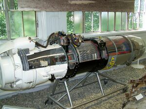
Klimov VK-1F turbojet with afterburner. An afterburner is a propulsive duct in which high velocity exhaust from an engine turbine is converted into pressure in a diffuser. Afterburner fuel is burned with the oxygen in the dilution air which was not involved in the engine combustion process. The gas expands in a nozzle with an increase in velocity. The turbojet afterburner has the same three requirements as a ramjet, both being propulsive ducts. These are conversion of high velocity gas into pressure in a diffuser, combustion and expansion to a higher velocity in a nozzle. The turbojet/afterburner combination was sometimes considered in the late 1940s a turbo-ramjet.[34][35]
![Pratt & Whitney J57 turbojet (1/4 scale model). A turbojet uses its thermodynamic cycle gas as its propelling jet. The jet velocity exceeds the speed of a subsonic aircraft by too great an amount to be an economical method of subsonic aircraft propulsion. The purpose behind the jet engine is to convert fuel energy into kinetic energy of the cycle air but after the thrust-producing momentum has appeared the unwanted byproduct is the wake velocity which results in kinetic energy loss, known as residual velocity loss (RVL). The wake velocity behind a turbojet-powered aircraft at subsonic speed is about 600 mph. At maximum propeller-driven speeds, the wake velocity behind the propeller it replaced as a thrust producer is about 10 mph with an insignificant RVL.[32] It is impossible to transform completely the kinetic energy acquired inside the engine into thrust work. The whole increase in kinetic energy obtained inside the engine is expended in thrust work and losses of kinetic energy outside the engine. There is thus kinetic energy inside the engine which will remain unused. In the case of the stationary engine before take-off the whole kinetic energy turns into losses since the thrust force does no work.[33]](/wiki/File:Pratt_%26_Whitney_JT3.jpg)
Since the introduction into service of the bypass principle in xx a progressively greater proportion of bypass air compared to that passing through the power-producing core has been enabled by increases in core power per pound a second of core airflow (specific core power).
A statement which illustrates the connection between the fan and core engine of a high bypass engine is attributed to Moran.[36] "The fan provides THRUST (sic!). The Core provides the power to operate the Fan + some thrust." The equivalent may be said of the piston engine/propeller combination. "The propeller provides thrust. The engine provides the power to operate the propeller + some thrust (from the exhaust stubs)." The similarity between the two technologies is that the functions of the power producer and the thrust producer are separated. The thermodynamic and propulsive efficiencies are independent. For the turbojet though, any improvement which raised the cycle pressure ratio or turbine inlet temperature also raised the jet pipe temperature and pressure giving a higher jet velocity relative to aircraft velocity. As the thermal efficiency went up the propulsive efficiency went down. This interdependence was broken with the bypass engine.
-
![Turbofan (CF-6) inlet and fan. The core flow area, 1/6th, is visible through the fan. A comparison of how effective the subsonic inlet is at compressing air compared with the fan is given by inlet ram and fan temperature rises for a CFM56 of about 30 and 40 °F at 0.85 Mn cruise.[3] Temperature rise is connected to pressure rise by the losses incurred in the way the compression is achieved and all three are visually apparent on a T~s diagram.](/wiki/images/thumb/d/d2/10%2B27_German_Air_Force_Luftwaffe_Airbus_A310-304_MRTT_General_Electric_CF6-80C2_engine_ILA_Berlin_2016_01.jpg/505px-10%2B27_German_Air_Force_Luftwaffe_Airbus_A310-304_MRTT_General_Electric_CF6-80C2_engine_ILA_Berlin_2016_01.jpg) Turbofan (CF-6) inlet and fan. The core flow area, 1/6th, is visible through the fan. A comparison of how effective the subsonic inlet is at compressing air compared with the fan is given by inlet ram and fan temperature rises for a CFM56 of about 30 and 40 °F at 0.85 Mn cruise.[3] Temperature rise is connected to pressure rise by the losses incurred in the way the compression is achieved and all three are visually apparent on a T~s diagram.
Turbofan (CF-6) inlet and fan. The core flow area, 1/6th, is visible through the fan. A comparison of how effective the subsonic inlet is at compressing air compared with the fan is given by inlet ram and fan temperature rises for a CFM56 of about 30 and 40 °F at 0.85 Mn cruise.[3] Temperature rise is connected to pressure rise by the losses incurred in the way the compression is achieved and all three are visually apparent on a T~s diagram. -
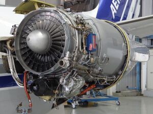
 Turbofan (IAE V2500) showing machinery needed to transfer energy from the core to bypass air which flows along the cutaway bypass duct. Those parts are the 5-stage turbine, extreme right identified with tip shroud rings, and the fan, extreme left. These parts introduce their own losses to the engine in achieving a gain in propulsive efficiency.
 -
 V2500 low pressure turbine. Part of the power from this turbine drives the inner part of the fan and 3 booster stages which contribute to the performance of the core. The other part transfers energy to the bypass air by driving the much larger outer part of the fan.
 -
![Turbofan (Trent) showing core nozzle and turbine blades, and bypass nozzle and fan bypass stators. The two nozzle wakes are made up of the waste which goes with thrust production. Both have residual velocity loss from their kinetic energy which is accounted for by pr eff. The core has heat rejected from the thermodynamic cycle and component losses. Also from the core part of the propulsion system, i.e. the nozzle and the LPT losses associated with the fan bypass flow. The fan nozzle passes the heat losses from the bypass propulsion system, i.e. the fan outer entropy generation, entropy production from the bypass duct pressure loss and the nozzle.[37]](/wiki/images/thumb/e/e9/Rolls-Royce_Trent_XWB_on_Airbus_A350-941_F-WWCF_MSN002_ILA_Berlin_2016_09_square-crop.jpg/337px-Rolls-Royce_Trent_XWB_on_Airbus_A350-941_F-WWCF_MSN002_ILA_Berlin_2016_09_square-crop.jpg) Turbofan (Trent) showing core nozzle and turbine blades, and bypass nozzle and fan bypass stators. The two nozzle wakes are made up of the waste which goes with thrust production. Both have residual velocity loss from their kinetic energy which is accounted for by pr eff. The core has heat rejected from the thermodynamic cycle and component losses. Also from the core part of the propulsion system, i.e. the nozzle and the LPT losses associated with the fan bypass flow. The fan nozzle passes the heat losses from the bypass propulsion system, i.e. the fan outer entropy generation, entropy production from the bypass duct pressure loss and the nozzle.[37]
Turbofan (Trent) showing core nozzle and turbine blades, and bypass nozzle and fan bypass stators. The two nozzle wakes are made up of the waste which goes with thrust production. Both have residual velocity loss from their kinetic energy which is accounted for by pr eff. The core has heat rejected from the thermodynamic cycle and component losses. Also from the core part of the propulsion system, i.e. the nozzle and the LPT losses associated with the fan bypass flow. The fan nozzle passes the heat losses from the bypass propulsion system, i.e. the fan outer entropy generation, entropy production from the bypass duct pressure loss and the nozzle.[37] -
 Low bypass turbofan (Turbo-Union RB199) with afterburner. Visible at the left is the bypass duct surrounding the turbines. For the afterburner can be seen the bypass fuel injectors and bypass flame holders and core flameholder in the centre. The core fuel injection is unseen upstream. Reliable burning in the bypass air, which can be as cold as 300 K, is guaranteed by collecting some of the turbine exhaust stream to heat the bypass flameholders. The buckets shown half-way between deployed and stowed positions are for the thrust reverser.
![Turbofan (CF-6) inlet and fan. The core flow area, 1/6th, is visible through the fan. A comparison of how effective the subsonic inlet is at compressing air compared with the fan is given by inlet ram and fan temperature rises for a CFM56 of about 30 and 40 °F at 0.85 Mn cruise.[3] Temperature rise is connected to pressure rise by the losses incurred in the way the compression is achieved and all three are visually apparent on a T~s diagram.](/wiki/File:10%2B27_German_Air_Force_Luftwaffe_Airbus_A310-304_MRTT_General_Electric_CF6-80C2_engine_ILA_Berlin_2016_01.jpg)

.JPG)
![Turbofan (Trent) showing core nozzle and turbine blades, and bypass nozzle and fan bypass stators. The two nozzle wakes are made up of the waste which goes with thrust production. Both have residual velocity loss from their kinetic energy which is accounted for by pr eff. The core has heat rejected from the thermodynamic cycle and component losses. Also from the core part of the propulsion system, i.e. the nozzle and the LPT losses associated with the fan bypass flow. The fan nozzle passes the heat losses from the bypass propulsion system, i.e. the fan outer entropy generation, entropy production from the bypass duct pressure loss and the nozzle.[37]](/wiki/File:Rolls-Royce_Trent_XWB_on_Airbus_A350-941_F-WWCF_MSN002_ILA_Berlin_2016_09_square-crop.jpg)

Thrust and fuel consumption
Thrust and fuel consumption are key performance indicators for a jet engine. Improvements in thrust and fuel consumption are widely quoted for a new engine design compared to a previous to show that new technology has been incorporated which reduces fuel consumption. As an example the Pearl 10X turbofan has been reported as producing 8% more thrust and using 5% less fuel than the BR725.[38] Thrust and fuel consumption are combined in a single measure, specific fuel consumption (SFC), which reflects the level of technology used in the engine since it is fuel needed to produce one pound or Newton of thrust regardless of engine size. Two engines separated by about fifty years of gaining knowledge in jet engine design, the Pratt & Whitney JT3C and the Pratt & Whitney 1100G, illustrate a 50% reduction in SFC from 26 to 13 mg/Ns.[39]
Thrust is developed inside the engine as the components energize the gas stream.[40] The same thrust value manifests itself without consideration of what is happening inside the engine. Treating the engine as a black box thrust is calculated knowing the mass flow rate and velocity of the air entering the engine and the increased velocity of the exhaust leaving the engine. Observing this increase implies a rearward accelerating force has been applied to the gas inside the engine. Thrust is the equal and opposite reaction on the engine internal parts which is transferred to the aircraft through the engine mounts.
Engine pressure ratio (EPR), low-pressure compressor speed (N1) and exhaust gas temperature (EGT)


EPR or N1 are used as cockpit indicators for thrust because one or the other, depending on the preference of the engine maker, is a valid alternative for thrust which is not measured in an aircraft. As such they are known as thrust setting parameters. N1 is preferred by General Electric Aviation and CFM International and EPR is preferred by Pratt & Whitney and Rolls-Royce. The meaning of EPR for a turbojet, compares the pressure in the jetpipe to the pressure outside the engine and the rise in pressure is the result of the pumping action of the engine. The combined action of the engine and an added nozzle is to produce thrust. The function of the basic engine (compressor, combustor and turbine) is to pump air to a pressure higher than that of the surrounding air.[41] It is then accelerated by passing it through a constricted area known as a nozzle. For a bypass engine with two separate nozzles the pressures in each are weighted relative to the nozzle areas. As such the Rolls-Royce RB211 thrust indicator is known as integrated EPR (IEPR). Thrust is easily controlled by regulating airflow and since all of the airflow is pumped by the fan N1 is used for setting thrust by General Electric Aviation.[42]
The EGT is a cockpit indicator for fuel flow since the fuel burned in the combustor determines the turbine entry temperature, which cannot be reliably measured, and EGT is a suitable alternative. Any deterioration from the engine as-new condition will require more fuel, resulting in higher temperature gas, to produce the thrust. At the take-off EPR, for example, the fuel flow and hence EGT rise with time in service as the engine deteriorates from its as-new condition. It progressively uses more fuel, until parts have to be replaced to restore the original lower operating temperature and reduce the cost of buying fuel.[43]
Cockpit performance indicators may be misleading
Although EPR is directly related to thrust over the flight envelope American Airlines experience with their first jet engines, Pratt & Whitney JT3C, was marred by instrumentation problems so the cockpit reading was questioned and other parameters, FF and N1, were used by flight personnel in desperation.[44]
EPR is based on pressure measurements with the sampling tubes vulnerable to getting blocked. Air Florida Flight 90 crashed on take-off in snow and icing conditions. The required take-off thrust was 14,500 lb which would normally be set by advancing the thrust levers to give an EPR reading of 2.04. Due to EPR probe icing the value set, i.e. 2.04, was erroneous and actually equivalent to 1.70 which gave an actual thrust of only 10,750 lb. The slower acceleration took 15 seconds longer than normal to reach lift off speed and contributed to the crash.[45]
EGT readings can also be misleading. The temperature of the gas leaving the turbine increases with engine use as parts become worn but the Strategic Air Command approved J57 and TF33 engines for flight without knowing they had bent and broken turbine parts. They were misled by low-reading EGT which indicated, when taken at face value, that the engines were in acceptable condition. It was found that the EGT probes were not positioned correctly to sample a representative gas temperature for the true condition of the engine.[46]
Performance improvement
Performance from an SFC viewpoint, rather than weight or size say, is the overall energy conversion efficiency of the whole powerplant, or the degree to which waste is minimized. The overall efficiency of the whole powerplant depends on the efficiencies of the constituent parts which all produce waste.
Performance improvement of the jet engine, first as a turbojet and then as a turbofan, has come from continuous increases in pressure ratio (PR) and component efficiencies, reduced pressure losses and from materials development which, together with cooling technologies, has allowed higher turbine inlet temperatures (TIT). It has also come from reduced leakage from the gas path because only the gas flow over the airfoil surfaces contributes to thrust. Increases in TIT mean a higher power output which for a turbojet leads to too high exhaust velocities for subsonic flight. For subsonic aircraft the high core power available from increased TIT is used to drive a large fan which adds less kinetic energy to a large amount of air.[47] Kinetic energy is the unwanted byproduct, known as residual velocity loss, of increasing momentum which produces thrust. The aim of the propulsion engineer is to minimize the conversion or degradation of energy into heat rather than thrust work. Piston engines used some of their waste heat with turbocharging and turbo-compounding. Some was used for thrust from rearwards facing exhaust stubs. The waste heat from a jet engine cannot be used so performance is improved by reducing the amount produced while the air is passing through the engine. This includes loss in total pressure from entropy production in ducts as explained by Sullivan:[48]
Irreversibility or entropy production is a measure of the destruction in the conversion of energy from a high quality form to a low quality form. Fluid flow in a duct with high kinetic energy is a high quality energy datum and the boundary layer converts some of the kinetic energy to a lower quality form thermal energy.
A reason for increasing bypass when core power has been increased is given by Hartmann:[49]
Higher specific output, ie greater conversion of heat from fuel to KE of a jet, is poor exploitation of the KE needed for the production of thrust due to high energy losses at the outlet.
Increased overall pressure ratio
Increased pressure ratio is an improvement to the thermodynamic cycle because combustion at a higher pressure has a reduced entropy rise which is the basic reason for pursuing higher pressure ratios in the jet engine cycle which is known as the Brayton cycle.[50] Increased pressure ratio can be achieved by using more stages or increasing the stage pressure ratio. The significance of higher pressure ratio to fuel consumption was demonstrated in 1948 when the J57 (12:1) was selected for the Boeing B-52 Stratofortress in place of a turboprop.[51] Boeing previous experience with turbojet specific fuel consumptions up to that time was the General Electric J47 (5.4:1), used in the Boeing B-47 Stratojet, which initially led to the turboprop decision.
The radial flow compressor was widely used for early turbojet engines but advantages in performance that came with the axial compressor in terms of pressure ratio, SFC, specific weight and thrust for each square foot of frontal area were presented in 1950 by Hayne Constant[52] However, a radial flow compressor is still the best choice for small turbofans as the last high pressure stage because the alternative very small axial stages would be too easily damaged and inefficient with tip clearance being significant compared to the blade height.[53]
-
 Early turbojet, de Havilland Goblin, radial flow compressor with pressure ratio 3.3:1, 1942.
 -
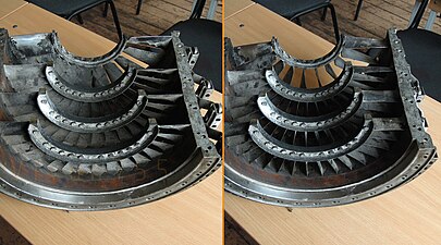
![Two stages of centrifugal compressor as shown here in the Rolls-Royce Dart turboprop were used in a jet engine, the Garrett F109 turbofan with a pressure ratio of 13:1.[54]](/wiki/images/thumb/2/2b/Gearbox_and_compressors_of_sectioned_Rolls-Royce_Dart_turboprop.jpg/338px-Gearbox_and_compressors_of_sectioned_Rolls-Royce_Dart_turboprop.jpg) Two stages of centrifugal compressor as shown here in the Rolls-Royce Dart turboprop were used in a jet engine, the Garrett F109 turbofan with a pressure ratio of 13:1.[54]
Two stages of centrifugal compressor as shown here in the Rolls-Royce Dart turboprop were used in a jet engine, the Garrett F109 turbofan with a pressure ratio of 13:1.[54] -
 Early turbojet, General Electric J47, 1947. The 11 stage compressor has a pressure ratio of 5.4:1.
 -
![IAE V2500 turbofan (1987) with overall pressure ratio of about 35:1 which is generated by 1 fan, 4 low pressure and 10 high pressure compressor stages. By 2016 overall pressure ratio had reached 60:1 in the General Electric GE9X.[55]](/wiki/images/thumb/f/fd/IAE_V2500_engine_cutaway_model_2010_The_Sky_and_Space.jpg/338px-IAE_V2500_engine_cutaway_model_2010_The_Sky_and_Space.jpg) IAE V2500 turbofan (1987) with overall pressure ratio of about 35:1 which is generated by 1 fan, 4 low pressure and 10 high pressure compressor stages. By 2016 overall pressure ratio had reached 60:1 in the General Electric GE9X.[55]
IAE V2500 turbofan (1987) with overall pressure ratio of about 35:1 which is generated by 1 fan, 4 low pressure and 10 high pressure compressor stages. By 2016 overall pressure ratio had reached 60:1 in the General Electric GE9X.[55] -
Pratt & Whitney Canada PW500 business jet PW530 turbofan showing HP compressor with 2 axial and centrifugal compressor last stage with back sweep and pipe diffusers. Overall pressure ratio about 13:1
-
 Honeywell/ITEC F124 jet trainer/light combat aircraft turbofan showing HP compressor with 4 axial and centrifugal last stage with high backsweep, splitter blades and leading edge sweep. Overall pressure ratio 19.4:1 from 3 axial fan, 4 axial HP and 1 centrifugal.

![Two stages of centrifugal compressor as shown here in the Rolls-Royce Dart turboprop were used in a jet engine, the Garrett F109 turbofan with a pressure ratio of 13:1.[54]](/wiki/File:Gearbox_and_compressors_of_sectioned_Rolls-Royce_Dart_turboprop.jpg)

.jpg)
Enabling technologies for high overall pressure ratio
The axial compressor has a geometry applicable to its high speed design condition at which the airflow approaches all the blading with little or no incidence, a requirement to keep flow losses to a minimum. As soon as conditions change from the design point the blade incidence angle will change away from a low-loss value and ultimately the compressor will no longer operate in a stable manner. The deviations from design are acceptable if the compressor doesn't have to raise the air pressure too much, say to 5 atmospheres. For greater values variable features have to be incorporated which change the compressor geometry below the design speed. Engines that came after the J47 with its 5.4:1 PR had compressors with higher PRs that needed some form of variable feature which operated at low speeds to prevent front stage stall and flutter failure and rear stage choking. These were valves which opened to release air when all the stages could not pass the same flow and variable angle vanes to maintain acceptable velocity triangles made up from the velocity of the approaching air, blade velocity and the relative velocity of air to blade. Alternatively the compressor was split into two separately rotating compressors[56] each with a low pressure ratio such as the J57 with 3.75 LP x 3.2 HP = 12:1 overall.[57] Bleed valves, variable blade angles and split compressors are used together on modern engines to achieve high pressure ratios. The Rolls-Royce Trent 700 from the 1990s, with a pressure ratio of 36:1 and 3 separate compressor rotors, needs 3 rows of variable blades and 7 bleed valves.
In the beginning higher pressure ratios had to be obtained with many stages because stage pressure ratios were low, about 1.16 for the J79 compressor which needed 17 stages.[58] Modern compressors have a higher PR per stage and still require the same variable features. The CFM International LEAP engine HP compressor with a PR 22:1 from 10 stages needs variable inlet guide vanes and 4 stages of variable stator vanes. The overall pressure ratio for an engine is limited by the temperature that goes with it. A compressor outlet temperature of about 900 K is the limit which is determined by material suitability in terms of weight and cost.[59]
-
![Pratt & Whitney JT3 (1/4th scale) with 12:1 pr, an example of an early jet engine with a split compressor. It also needed starting/low speed bleed overboard from between the two compressors, closed above 90% N2.[60] A bleed valve vent with blue-painted mesh guard (half removed) is visible.](/wiki/images/thumb/1/18/Pratt_%26_Whitney_JT3.jpg/624px-Pratt_%26_Whitney_JT3.jpg) Pratt & Whitney JT3 (1/4th scale) with 12:1 pr, an example of an early jet engine with a split compressor. It also needed starting/low speed bleed overboard from between the two compressors, closed above 90% N2.[60] A bleed valve vent with blue-painted mesh guard (half removed) is visible.
Pratt & Whitney JT3 (1/4th scale) with 12:1 pr, an example of an early jet engine with a split compressor. It also needed starting/low speed bleed overboard from between the two compressors, closed above 90% N2.[60] A bleed valve vent with blue-painted mesh guard (half removed) is visible. -
![Rolls-Royce Avon early jet engine showing 1 of 2 sets of 3 valves at the top and 1 of 2 valves at the bottom which release some air from the compressor, pressure ratio 7.45:1, for starting and low speed running. Also visible at the front is the row of bearings for the variable inlet guide vanes.[61]](/wiki/images/thumb/5/5a/Jet_engine%2C_cutaway_%2827441073466%29.jpg/384px-Jet_engine%2C_cutaway_%2827441073466%29.jpg) Rolls-Royce Avon early jet engine showing 1 of 2 sets of 3 valves at the top and 1 of 2 valves at the bottom which release some air from the compressor, pressure ratio 7.45:1, for starting and low speed running. Also visible at the front is the row of bearings for the variable inlet guide vanes.[61]
Rolls-Royce Avon early jet engine showing 1 of 2 sets of 3 valves at the top and 1 of 2 valves at the bottom which release some air from the compressor, pressure ratio 7.45:1, for starting and low speed running. Also visible at the front is the row of bearings for the variable inlet guide vanes.[61] -
 General Electric CJ805 pr 13:1, showing actuation mechanism for variable inlet guide vanes and 6 stages of variable stators with varying angles to suit starting and low speed running.
 -
 General Electric J79/CJ805 compressor showing, just visible at compressor case horizontal split flange, variable stators, evident by circular end feature for rotation, for starting and low speed running
 -
 J79/CJ805 front compressor stages with VSV - shows air passage narrowing as volume of each pound of air gets smaller as pressure increases
 -
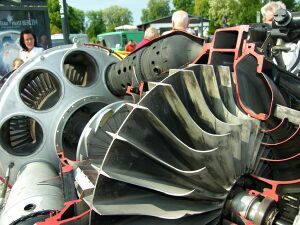
 These photographs of a damaged compressor case illustrate the angular travel of variable stators and the meaning of the terminology, open and closed. It shows stator vanes closed for starting and low speed running (left photograph) and open for higher speeds. Klimov TV2-117 turboshaft compressor with pr 6.6:1
 -
![Pratt & Whitney J58 Bleed required from the compressor, pr 9:1. 4th stage bleed doors required for engine starting and venting to the nacelle are visible immediately forward of the top bleed tube. 3 of 6 tubes for 4th stage bypass bleed to the afterburner required at low corrected speeds caused by high Mach ram temperature.[62]](/wiki/images/thumb/a/a5/SR-71A_at_Joe_Davies_Heritage_Airpark_-_J58_Jet_Engine._-_panoramio.jpg/300px-SR-71A_at_Joe_Davies_Heritage_Airpark_-_J58_Jet_Engine._-_panoramio.jpg) Pratt & Whitney J58 Bleed required from the compressor, pr 9:1. 4th stage bleed doors required for engine starting and venting to the nacelle are visible immediately forward of the top bleed tube. 3 of 6 tubes for 4th stage bypass bleed to the afterburner required at low corrected speeds caused by high Mach ram temperature.[62]
Pratt & Whitney J58 Bleed required from the compressor, pr 9:1. 4th stage bleed doors required for engine starting and venting to the nacelle are visible immediately forward of the top bleed tube. 3 of 6 tubes for 4th stage bypass bleed to the afterburner required at low corrected speeds caused by high Mach ram temperature.[62] -
![J58 2-position trailing edge flaps give the variable inlet guide vane function required to prevent front stage compressor blade flutter (vibration).[63]](/wiki/images/thumb/5/56/Pratt_%26_Whitney_J58_Turbojet.jpg/300px-Pratt_%26_Whitney_J58_Turbojet.jpg) J58 2-position trailing edge flaps give the variable inlet guide vane function required to prevent front stage compressor blade flutter (vibration).[63]
J58 2-position trailing edge flaps give the variable inlet guide vane function required to prevent front stage compressor blade flutter (vibration).[63] -
PW530 business jet turbofan with bleed valve, seen above the first stage blades of the high pressure compressor. It passes compressed air from the impeller entry into the bypass duct at low speeds.
-
 Variable inlet guide vanes are used on modern engines. Variable trailing edge flaps, colored brown, are visible on this General Electric F414.
 -
 CFM LEAP engine showing actuating mechanisms for high pressure compressor inlet guide vanes and stators on the first 4 stages.
![Rolls-Royce Avon early jet engine showing 1 of 2 sets of 3 valves at the top and 1 of 2 valves at the bottom which release some air from the compressor, pressure ratio 7.45:1, for starting and low speed running. Also visible at the front is the row of bearings for the variable inlet guide vanes.[61]](/wiki/File:Jet_engine,_cutaway_(27441073466).jpg)


![Pratt & Whitney J58 Bleed required from the compressor, pr 9:1. 4th stage bleed doors required for engine starting and venting to the nacelle are visible immediately forward of the top bleed tube. 3 of 6 tubes for 4th stage bypass bleed to the afterburner required at low corrected speeds caused by high Mach ram temperature.[62]](/wiki/File:SR-71A_at_Joe_Davies_Heritage_Airpark_-_J58_Jet_Engine._-_panoramio.jpg)
![J58 2-position trailing edge flaps give the variable inlet guide vane function required to prevent front stage compressor blade flutter (vibration).[63]](/wiki/File:Pratt_%26_Whitney_J58_Turbojet.jpg)
,_install_a_fan_module_onto_a_F414_jet_engine.jpg)
.jpg)
Increased stage pressure ratio
Air compression in a gas turbine is achieved by converting a proportion of the kinetic energy (compressor rotor generated, either by a centrifugal impeller or an axial row) of the air into static pressure one stage at a time. Most early jet engines used a single-stage centrifugal compressor with pressure ratios such as 3.3:1 (de Havilland Goblin). Higher pressure ratios came with the axial compressor because although stage pressure ratios were very low in comparison (1.17:1 BMW 003)[64] more stages could be used as required for a higher overall pressure ratio. More advanced centrifugal stages are used in small turbofans as the last high-pressure stage behind axial stages (Pratt & Whitney Canada PW300 and others). The same technology level produces 8:1 when used as the only stage in Pratt & Whitney PW200 helicopter engines.[65] A centrifugal stage consists of an impeller and diffuser vanes,[66] or alternatively diffuser pipes[67] which are considered to give less blockage as the static pressure rises with diffusion.[68]
An axial compressor consists of alternating rows of rotating and stationary diffusers,[69] each pair being a stage. These diffusers are diverging as necessary for subsonic flow.[70] The channel formed by adjacent blades, amount of diffusion, is adjusted by varying their angle relative to tangential, known as stagger angle.[71] More diffusion gives a higher pressure ratio but flow in compressors is very susceptible to flow separation because it is going against a rising pressure (gas naturally flows from high to low pressure). Stage pressure ratio had increased by 2016 such that 11 stages could achieve 27:1 (GE9X high pressure compressor).[55]
Low aspect ratio compressor blades, with their better efficiency both aerodynamically and structurally, were introduced in the 1950s turbojet the Tumansky R-11, and subsequently examples of wide chord fan blades introduced in 1983 in the Garrett TFE731-5[72] and in 1984 in the RB211-535E4[73] and Pratt & Whitney Canada JT15D-5.[74]
-
1942 de Havilland Goblin with single centrifugal stage with pressure ratio 3.3:1
-
 1940 BMW 003 with stage pressure ratio 1.17:1 for each of 7 stages
 -
 A centrifugal stage has diffuser vanes, which slow the airflow after it leaves the tip of the impeller, visible in this Turbomeca Artouste engine. They contribute to the stage pressure ratio.
 -
 Klimov VK-1 This photograph shows typical centrifugal stage cambered diffuser vanes, but on the small cooling impeller for the internal air system. For the engine double-sided centrifugal compressor stage the equivalent have not been made visible with the sectioning.
 -
![Pratt & Whitney Canada JT15D impeller with 7:1 pressure ratio would have required 6 or 7 axial stages in its place.[75] This centrifugal stage uses pipe diffusers rather than diffuser vanes. The fan blades are not installed in the fan hub which is in front of the small booster blades.](/wiki/images/thumb/7/74/Pratt_%26_Whitney_JT15D-4_two_shaft_engine_-_Malaga_Airport_Exposition_-_October_2022_2.jpg/300px-Pratt_%26_Whitney_JT15D-4_two_shaft_engine_-_Malaga_Airport_Exposition_-_October_2022_2.jpg) Pratt & Whitney Canada JT15D impeller with 7:1 pressure ratio would have required 6 or 7 axial stages in its place.[75] This centrifugal stage uses pipe diffusers rather than diffuser vanes. The fan blades are not installed in the fan hub which is in front of the small booster blades.
Pratt & Whitney Canada JT15D impeller with 7:1 pressure ratio would have required 6 or 7 axial stages in its place.[75] This centrifugal stage uses pipe diffusers rather than diffuser vanes. The fan blades are not installed in the fan hub which is in front of the small booster blades.


.jpg)
![Pratt & Whitney Canada JT15D impeller with 7:1 pressure ratio would have required 6 or 7 axial stages in its place.[75] This centrifugal stage uses pipe diffusers rather than diffuser vanes. The fan blades are not installed in the fan hub which is in front of the small booster blades.](/wiki/File:Pratt_%26_Whitney_JT15D-4_two_shaft_engine_-_Malaga_Airport_Exposition_-_October_2022_2.jpg)
-
 This unidentified aircraft gas turbine shows axial compressor details, the blade passages where diffusion takes place in the rotor blades and stationary stators (not visible but their orientation is evident from the appearance of the welds fixing the vanes in place). The first row of vanes are the inlet guide vanes shown with a horizontal orientation which means the air leaves the vanes in the axial direction. Immediately following are the spinning rotor blades which the air has to hit within a narrow range of low-loss angles. The apparent mismatch of directions is resolved in reality because the axial velocity and the tangential or peripheral velocity of the fast-moving blades add in their defining velocity triangle to give the required narrow incidence range relative to the blades.
 -
![Velocity triangles are used to show the velocity of the air relative to the stationary vanes and rotating blades. This figure shows the diffusing shape for the airflow between the blades, the exit area B is greater than the entry area A for the moving rotor blades (loopschoepen) and stationary vanes (leidschoepen). It also shows the construction of the velocity triangles which determine the angle the air strikes the leading edges. W1 is the velocity relative to the blade moving at u and is aligned at a low-loss angle with the first rotor, C2 is similarly aligned with the stationary vane, W3 is aligned with the second rotor. Velocity triangles allow the mixing of moving and stationary viewpoints. For example, the air is moving at velocity relative to rotor blade as it leaves the trailing edge and the triangle, with the blade velocity, converts to head-on velocity as it strikes a stationary vane.[76]](/wiki/images/thumb/0/06/Compressor_stage.JPG/380px-Compressor_stage.JPG) Velocity triangles are used to show the velocity of the air relative to the stationary vanes and rotating blades. This figure shows the diffusing shape for the airflow between the blades, the exit area B is greater than the entry area A for the moving rotor blades (loopschoepen) and stationary vanes (leidschoepen). It also shows the construction of the velocity triangles which determine the angle the air strikes the leading edges. W1 is the velocity relative to the blade moving at u and is aligned at a low-loss angle with the first rotor, C2 is similarly aligned with the stationary vane, W3 is aligned with the second rotor. Velocity triangles allow the mixing of moving and stationary viewpoints. For example, the air is moving at velocity relative to rotor blade as it leaves the trailing edge and the triangle, with the blade velocity, converts to head-on velocity as it strikes a stationary vane.[76]
Velocity triangles are used to show the velocity of the air relative to the stationary vanes and rotating blades. This figure shows the diffusing shape for the airflow between the blades, the exit area B is greater than the entry area A for the moving rotor blades (loopschoepen) and stationary vanes (leidschoepen). It also shows the construction of the velocity triangles which determine the angle the air strikes the leading edges. W1 is the velocity relative to the blade moving at u and is aligned at a low-loss angle with the first rotor, C2 is similarly aligned with the stationary vane, W3 is aligned with the second rotor. Velocity triangles allow the mixing of moving and stationary viewpoints. For example, the air is moving at velocity relative to rotor blade as it leaves the trailing edge and the triangle, with the blade velocity, converts to head-on velocity as it strikes a stationary vane.[76] -
 General Electric J85 turbojet compressor showing the axial spacing between rotating and stationary blades required to prevent blades touching when they bend during surges.
 -
![This diagram shows some features in the complex flowfield in an axial compressor rotor. They are loss mechanisms which generate entropy. The flow is unsteady due to the relative motion between each row of moving and stationary blades. The flow patterns shown are known as secondary flow and are responsible for half the losses in a compressor.[77]](/wiki/images/thumb/e/e9/COMBUSTOR_SECTIONS_-_NARA_-_17447547.jpg/288px-COMBUSTOR_SECTIONS_-_NARA_-_17447547.jpg) This diagram shows some features in the complex flowfield in an axial compressor rotor. They are loss mechanisms which generate entropy. The flow is unsteady due to the relative motion between each row of moving and stationary blades. The flow patterns shown are known as secondary flow and are responsible for half the losses in a compressor.[77]
This diagram shows some features in the complex flowfield in an axial compressor rotor. They are loss mechanisms which generate entropy. The flow is unsteady due to the relative motion between each row of moving and stationary blades. The flow patterns shown are known as secondary flow and are responsible for half the losses in a compressor.[77] -
 Rolls-Royce Avon high aspect ratio (narrow) compressor blading typical in military engines until the 1970s.
 -
![1950's Tumansky R-11 low aspect ratio (wide) blading which preceded its introduction in other military engines by 20 years.[78]](/wiki/images/thumb/4/49/Strahltriebwerk_%2841509006890%29.jpg/337px-Strahltriebwerk_%2841509006890%29.jpg) 1950's Tumansky R-11 low aspect ratio (wide) blading which preceded its introduction in other military engines by 20 years.[78]
1950's Tumansky R-11 low aspect ratio (wide) blading which preceded its introduction in other military engines by 20 years.[78]

![Velocity triangles are used to show the velocity of the air relative to the stationary vanes and rotating blades. This figure shows the diffusing shape for the airflow between the blades, the exit area B is greater than the entry area A for the moving rotor blades (loopschoepen) and stationary vanes (leidschoepen). It also shows the construction of the velocity triangles which determine the angle the air strikes the leading edges. W1 is the velocity relative to the blade moving at u and is aligned at a low-loss angle with the first rotor, C2 is similarly aligned with the stationary vane, W3 is aligned with the second rotor. Velocity triangles allow the mixing of moving and stationary viewpoints. For example, the air is moving at velocity relative to rotor blade as it leaves the trailing edge and the triangle, with the blade velocity, converts to head-on velocity as it strikes a stationary vane.[76]](/wiki/File:Compressor_stage.JPG)

![This diagram shows some features in the complex flowfield in an axial compressor rotor. They are loss mechanisms which generate entropy. The flow is unsteady due to the relative motion between each row of moving and stationary blades. The flow patterns shown are known as secondary flow and are responsible for half the losses in a compressor.[77]](/wiki/File:COMBUSTOR_SECTIONS_-_NARA_-_17447547.jpg)

![1950's Tumansky R-11 low aspect ratio (wide) blading which preceded its introduction in other military engines by 20 years.[78]](/wiki/File:Strahltriebwerk_(41509006890).jpg)
Fan efficiency
Fan blades on modern engines have a wide chord which replaced conventional narrow chord blades which needed snubbers, or shrouds, to prevent them vibrating to an unacceptable degree. Increasing the length of the chord by an amount which made the blade stiff enough to not require snubbers also made the blade more resistant to damage caused by bird, hail and ice ingestion,[79] and brought several unrelated benefits of improved efficiency, surge margin and noise reductions.[80] There is also a greater axial distance for centrifuging debris away from the compressor inlet to prevent erosion of the airfoil surfaces which lowers compressor efficiency.
-
 1960's Pratt & Whitney JT9D 92 inch diameter fan with long, narrow blades known as high aspect ratio. This type of blade was designed assuming the airflow was two-dimensional, i.e. along a chord line with no mass, momentum or energy exchanged along the length of the blade. They were superseded by wide chord blading when CFD was introduced which models the real flow around blades which is 3-dimensional.
 -
1970 Garrett TFE731 with an early example of a transonic (supersonic relative velocities over the outer part of the blade) fan designed with the help of three-dimensional computational fluid dynamics (CFD).[81]
-
 The 1967 Pratt & Whitney JT15D-1 to -4 fan with part-span shrouds and local stiffeners which reduce fan efficiency
 -
 Introduced in 1984 the Pratt & Whitney JT15D-5 with wide chord fan blades and shrouds and stiffeners deleted.
 -
![Rolls-Royce Trent 900 116 inch diameter fan. The fan has supersonic relative velocities in the outer half which result in shock waves in the passages. Visually evident are the blade leading edge sweep which changes from hub to tip from forward to backward to forward and the blade twist which varies from almost axial at the hub to almost circumferential at the tip. The shape of the blade positions the shock far enough behind the leading edge to prevent expulsion of the shockwave beyond the tip leading edge (prevents surge and flutter). Each radial section with its contribution to leading edge sweep and blade twist has its centrifugal force acting close to a radial line which minimizes stress due to rotation.[82][83]](/wiki/images/thumb/0/07/Rolls-Royce_Trent_900_front.jpg/300px-Rolls-Royce_Trent_900_front.jpg) Rolls-Royce Trent 900 116 inch diameter fan. The fan has supersonic relative velocities in the outer half which result in shock waves in the passages. Visually evident are the blade leading edge sweep which changes from hub to tip from forward to backward to forward and the blade twist which varies from almost axial at the hub to almost circumferential at the tip. The shape of the blade positions the shock far enough behind the leading edge to prevent expulsion of the shockwave beyond the tip leading edge (prevents surge and flutter). Each radial section with its contribution to leading edge sweep and blade twist has its centrifugal force acting close to a radial line which minimizes stress due to rotation.[82][83]
Rolls-Royce Trent 900 116 inch diameter fan. The fan has supersonic relative velocities in the outer half which result in shock waves in the passages. Visually evident are the blade leading edge sweep which changes from hub to tip from forward to backward to forward and the blade twist which varies from almost axial at the hub to almost circumferential at the tip. The shape of the blade positions the shock far enough behind the leading edge to prevent expulsion of the shockwave beyond the tip leading edge (prevents surge and flutter). Each radial section with its contribution to leading edge sweep and blade twist has its centrifugal force acting close to a radial line which minimizes stress due to rotation.[82][83]

.jpg)

![Rolls-Royce Trent 900 116 inch diameter fan. The fan has supersonic relative velocities in the outer half which result in shock waves in the passages. Visually evident are the blade leading edge sweep which changes from hub to tip from forward to backward to forward and the blade twist which varies from almost axial at the hub to almost circumferential at the tip. The shape of the blade positions the shock far enough behind the leading edge to prevent expulsion of the shockwave beyond the tip leading edge (prevents surge and flutter). Each radial section with its contribution to leading edge sweep and blade twist has its centrifugal force acting close to a radial line which minimizes stress due to rotation.[82][83]](/wiki/File:Rolls-Royce_Trent_900_front.jpg)
Combustion
The effects of heat transfer and friction in a combustor, both engine and afterburner, cause a loss of stagnation pressure and an increase in entropy. The loss in pressure is shown on a T~s diagram where it can be seen to reduce the area of the work part of the diagram. The pressure loss through a combustor has two contributions. One due to bringing the air from the compressor into the combustion area including through all the cooling holes (friction pressure loss), that is with air flowing but no combustion taking place. The addition of heat to the flowing gas adds another type of pressure loss (momentum pressure loss).
In addition to stagnation pressure loss the other measure of combustion performance is incomplete combustion. Combustion efficiency had always been close to 100% at high thrust levels meaning only small amounts of HC and CO are present, but big improvements had to be made near idle operation. In the 1990s reduction of nitrogen oxides (NOx) became the focus due to its contribution to smog and acid rain for example. Combustor technology for reducing NOx is the Rich burn, Quick mix, Lean burn (RQL)[84] introduced by Pratt & Whitney with the TALON (Technology for Advanced Low NOx) PW4098 combustor.[85] RQL technology is also used in the Rolls-Royce Phase 5 Trent 1000 combustor and the General Electric LEC (Low Emissions Combustor).[36]
Engine combustor configurations are reverse-flow separate, straight-through separate, can-annular (all three historic because the annular flow chamber gives more area and more even flow to the turbine), and modern annular and reverse-flow annular. Fuel preparation for combustion is either done by converting it into small drops (atomization) or heating it with air in tubes immersed in flame (vaporization).
Examples of early jet engines with centrifugal compressors, the Rolls-Royce Welland and General Electric J31, used reverse-flow combustors. More modern small jet engines incorporating a centrifugal final compressor stage also use reverse-flow combustors and range from the 1,000 lbf thrust Pratt & Whitney Canada PW600 in the 6,000 lb Eclipse 500 very light jet to the 7,000 lbf thrust Lycoming ALF 502 in the 97,000 lb British Aerospace 146 airliner.
-
General Electric J31 with ten reverse-flow combustors. Compressed air flows between the 18-8 stainless steel outer casing and inner Inconel flame tube, then through a series of holes to the inside of the tube where it mixes with fuel. Burning continues along the length and is complete before reversing direction to the turbine.[86]
-
![de Havilland Goblin with sixteen straight-through combustion chambers. Each consists of a flame tube enclosed in a pressure-tight outer casing. They are connected by tubes which balance the pressure and propagate the flame during start from the two tubes with igniters one of which is shown on a top tube.[87]](/wiki/images/thumb/5/58/Royal_Military_Museum_Brussels_2007_224.JPG/300px-Royal_Military_Museum_Brussels_2007_224.JPG) de Havilland Goblin with sixteen straight-through combustion chambers. Each consists of a flame tube enclosed in a pressure-tight outer casing. They are connected by tubes which balance the pressure and propagate the flame during start from the two tubes with igniters one of which is shown on a top tube.[87]
de Havilland Goblin with sixteen straight-through combustion chambers. Each consists of a flame tube enclosed in a pressure-tight outer casing. They are connected by tubes which balance the pressure and propagate the flame during start from the two tubes with igniters one of which is shown on a top tube.[87] -
Rolls-Royce Nene with nine combustion chambers. The cutaway is one of 2 chambers fitted with a flame igniter which places the igniter in a cooler location than directly in the hot gas stream. During a start atomized fuel from the small self-contained unit (orange-coloured solenoid shown) is ignited by its ignition plug and the flaming jet of fuel is projected into the main fuel spray from the burner. Combustion is propagated to all the chambers through interconnecting tubes.[88]
-
![Westinghouse J46 "walking stick" fuel vapouriser tubes in an annular combustor.[89] Fuel vaporization was also used in the Sapphire, Viper, Pegasus, Olympus 593, and RB211 engines. Otherwise engines use some form of atomizing nozzle[90] which converts fuel pressure in the fuel tube to kinetic energy in the combustor producing a well-atomized spray.](/wiki/images/thumb/7/75/Westinghouse_J46-WE-8_axial_flow_jet_engine_-_Hiller_Aviation_Museum_-_San_Carlos%2C_California_-_DSC03061.jpg/412px-Westinghouse_J46-WE-8_axial_flow_jet_engine_-_Hiller_Aviation_Museum_-_San_Carlos%2C_California_-_DSC03061.jpg) Westinghouse J46 "walking stick" fuel vapouriser tubes in an annular combustor.[89] Fuel vaporization was also used in the Sapphire, Viper, Pegasus, Olympus 593, and RB211 engines. Otherwise engines use some form of atomizing nozzle[90] which converts fuel pressure in the fuel tube to kinetic energy in the combustor producing a well-atomized spray.
Westinghouse J46 "walking stick" fuel vapouriser tubes in an annular combustor.[89] Fuel vaporization was also used in the Sapphire, Viper, Pegasus, Olympus 593, and RB211 engines. Otherwise engines use some form of atomizing nozzle[90] which converts fuel pressure in the fuel tube to kinetic energy in the combustor producing a well-atomized spray. -
Pratt & Whitney J57 with eight can-annular combustors, meaning the flame cans are separate but contained within the annular space between outer and inner casings. Each can was an annular combustion chamber in miniature with a central tube for cooling air and six burners arranged around it.[91]
-
 JT9D straight-through annular combustor, airflow from left to right. The atomizing fuel nozzle is a dual orifice or duplex type. The primary, or pilot flow, comes from a small hole (orifice) in the centre at low engine speeds through the fuel tube at the left. The secondary, or main flow, comes from a larger opening around it at higher speeds through the tube on the right. Airflow from the small compressor exit guide vane at the left enters an area-increasing diffuser which divides it into three parts. The centre flow enters the combustor and mixes with fuel. The outer and inner parts enter the combustor progressively through the holes shown completing the combustion and then diluting to give a final exit temperature suitable for the turbine.
 -
![The engine combustor needs the high velocity air leaving the compressor to be slowed significantly, which is done with an increase in flow area (diffuser), to a low Mn before combustion takes place to ensure low combustion pressure loss. A recirculation zone (shown by the circular airflow paths) has to be maintained near the fuel nozzle for initial combustion of the entering fuel to take place. This zone (the primary zone) is maintained by the two primary air paths, the swirl flow entering through swirl vanes (depicted by grey squares) around the fuel injector and the first row of primary air radial inflow holes. Combustion is completed with the intermediate air and the gas temperature is reduced with the dilution air to the value required for long life of the turbine.[92]](/wiki/images/thumb/4/49/Combustor_diagram_airflow.png/621px-Combustor_diagram_airflow.png) The engine combustor needs the high velocity air leaving the compressor to be slowed significantly, which is done with an increase in flow area (diffuser), to a low Mn before combustion takes place to ensure low combustion pressure loss. A recirculation zone (shown by the circular airflow paths) has to be maintained near the fuel nozzle for initial combustion of the entering fuel to take place. This zone (the primary zone) is maintained by the two primary air paths, the swirl flow entering through swirl vanes (depicted by grey squares) around the fuel injector and the first row of primary air radial inflow holes. Combustion is completed with the intermediate air and the gas temperature is reduced with the dilution air to the value required for long life of the turbine.[92]
The engine combustor needs the high velocity air leaving the compressor to be slowed significantly, which is done with an increase in flow area (diffuser), to a low Mn before combustion takes place to ensure low combustion pressure loss. A recirculation zone (shown by the circular airflow paths) has to be maintained near the fuel nozzle for initial combustion of the entering fuel to take place. This zone (the primary zone) is maintained by the two primary air paths, the swirl flow entering through swirl vanes (depicted by grey squares) around the fuel injector and the first row of primary air radial inflow holes. Combustion is completed with the intermediate air and the gas temperature is reduced with the dilution air to the value required for long life of the turbine.[92] -
J85 annular combustor, displayed rear-end up. When installed in the engine this open end is closed by the first stage turbine nozzle vane ring the flow area of which (together with the area of the exhaust nozzle) back pressures the compressor to control its pressure rise and flow rate as shown on a compressor map.
-
Rolls-Royce Turbomeca Adour military turbofan. There is a requirement to maintain a certain minimum pressure-loss in combustors, rather than reducing it as much as possible to minimize entropy production. It has to be maintained to prevent backflow in the turbine cooling circuits since cooling air from the HP compressor needs a lower pressure at the turbines in order to flow.[93][94] Cooling air from the compressor (blue) has to flow to the turbine area (nozzle guide vane painted orange). This is enabled by the drop in pressure which occurs in the combustor. Also evident is the increase in area from the compressor into the combustor which is necessary to slow the air.
![de Havilland Goblin with sixteen straight-through combustion chambers. Each consists of a flame tube enclosed in a pressure-tight outer casing. They are connected by tubes which balance the pressure and propagate the flame during start from the two tubes with igniters one of which is shown on a top tube.[87]](/wiki/File:Royal_Military_Museum_Brussels_2007_224.JPG)
![Westinghouse J46 "walking stick" fuel vapouriser tubes in an annular combustor.[89] Fuel vaporization was also used in the Sapphire, Viper, Pegasus, Olympus 593, and RB211 engines. Otherwise engines use some form of atomizing nozzle[90] which converts fuel pressure in the fuel tube to kinetic energy in the combustor producing a well-atomized spray.](/wiki/File:Westinghouse_J46-WE-8_axial_flow_jet_engine_-_Hiller_Aviation_Museum_-_San_Carlos,_California_-_DSC03061.jpg)

![The engine combustor needs the high velocity air leaving the compressor to be slowed significantly, which is done with an increase in flow area (diffuser), to a low Mn before combustion takes place to ensure low combustion pressure loss. A recirculation zone (shown by the circular airflow paths) has to be maintained near the fuel nozzle for initial combustion of the entering fuel to take place. This zone (the primary zone) is maintained by the two primary air paths, the swirl flow entering through swirl vanes (depicted by grey squares) around the fuel injector and the first row of primary air radial inflow holes. Combustion is completed with the intermediate air and the gas temperature is reduced with the dilution air to the value required for long life of the turbine.[92]](/wiki/File:Combustor_diagram_airflow.png)
Early tests on afterburning showed the pressure loss due to burning increased rapidly if the Mach number at entry to the combustion zone was more than 0.3. This is lower than the Mn leaving the turbine so a diffusing section is required to slow the gas before the flameholders where combustion begins and is maintained in the recirculation zone.[95] An early surprise in afterburner testing was that the fuel does not ignite of its own accord in the hot turbine exhaust so afterburners use various methods of ignition. A low enough Mn where the flame starts (0.2–0.25 EJ200[96]) and a big enough duct diameter for the burning zone are necessary to keep the loss in total pressure in the afterburner to an acceptably low level. As with the engine combustor the air has to be slowed down from the previous component by starting with a diffuser. Stabilization of the flame is achieved in the engine combustor using airflow only, obtaining flow reversal, for example, by using swirl vanes around the fuel injector combined with air entering through holes in the liner. Afterburners use obstructions to the flow known as bluff-body flameholders ('Vee' gutters). Afterburner fuel nozzles are situated upstream of the burning zone to allow atomized fuel to mix sufficiently with the turbine exhaust for the flame to spread across the duct from the flameholders.
There are pressure losses due to duct wall friction in all ducts but an afterburner has additional losses caused by flameholders and fuel supply tubes. The fundamental pressure loss, that due to burning, increases with Mn at entry to burning zone and with the amount of fuel burned in terms of the increase in temperature in the afterburner.[97]
Although there is no turbine to limit the temperature of an afterburner there is still a cooling air requirement for the duct liner and variable nozzle which is about 10% of the engine entry airflow. The oxygen in this air is not available for burning.[98]
-
 Tumansky R-11 turbojet afterburner flare (diffusing section) required to reduce the flow Mn before combustion takes place. The flare ends just behind the visible flameholders. Missing is the combustion section and exit nozzle.
 -
 Rolls-Royce Turbomeca Adour turbofan afterburner showing 4 concentric bluff-body flameholders, fuel supply tubes, 2 catalytic igniters, all of which are obstructions to the gas flow which cause a loss of total pressure due to friction from the added turbulence and flow separation. Also shown outside the afterburner are 2 of 8 nozzle operating links from 1 of 4 nozzle operating rams.
 -
 This view almost in-line with the gas flow path shows all the obstructions responsible for part of the total pressure loss in an afterburner. Downstream, beyond the flameholders, is the burning length of duct where pressure loss occurs with heat addition.
 -
![Adour afterburner rear view showing 4 concentric vapour gutters (flameholders) which supply fuel required for minimum boost, the majority of the fuel, known as fill fuel, for full boost comes from 4 concentric manifolds upstream of the gutters to produce flame across the whole afterburner except for cooling air along the duct surface. Also visible is the anti screech liner for preventing pressure fluctuations which can cause damage from overheating.[99]](/wiki/images/thumb/8/8a/Rear_view_of_afterburner_in_sectioned_Rolls-Royce_Turbom%C3%A9ca_Adour_turbofan.jpg/338px-Rear_view_of_afterburner_in_sectioned_Rolls-Royce_Turbom%C3%A9ca_Adour_turbofan.jpg) Adour afterburner rear view showing 4 concentric vapour gutters (flameholders) which supply fuel required for minimum boost, the majority of the fuel, known as fill fuel, for full boost comes from 4 concentric manifolds upstream of the gutters to produce flame across the whole afterburner except for cooling air along the duct surface. Also visible is the anti screech liner for preventing pressure fluctuations which can cause damage from overheating.[99]
Adour afterburner rear view showing 4 concentric vapour gutters (flameholders) which supply fuel required for minimum boost, the majority of the fuel, known as fill fuel, for full boost comes from 4 concentric manifolds upstream of the gutters to produce flame across the whole afterburner except for cooling air along the duct surface. Also visible is the anti screech liner for preventing pressure fluctuations which can cause damage from overheating.[99] -
 Adour afterburner showing nozzle area operating links and variable nozzle in 'no afterburning' or closed position. The air mass flow rate through the engine is not changed with the afterburner in operation because the area is increased to allow the increased volume hotter gas to escape.
 -
 Adour nozzles in afterburning or open position.
_used_in_MiG-21_and_Yak_28_at_Flugausstellung_Hermeskeil,_pic1.JPG)
.jpg)
.jpg)
![Adour afterburner rear view showing 4 concentric vapour gutters (flameholders) which supply fuel required for minimum boost, the majority of the fuel, known as fill fuel, for full boost comes from 4 concentric manifolds upstream of the gutters to produce flame across the whole afterburner except for cooling air along the duct surface. Also visible is the anti screech liner for preventing pressure fluctuations which can cause damage from overheating.[99]](/wiki/File:Rear_view_of_afterburner_in_sectioned_Rolls-Royce_Turbom%C3%A9ca_Adour_turbofan.jpg)


Reduced pressure loss in ducts
Air passing through the engine goes through two components where velocities need to be high, of the order of the speed of sound. They are the components in which work is done, the compressor and turbine. In all the remaining components no work is done and the need to reduce pressure losses requires lower Mach numbers. These components are the engine combustor and afterburner, and the connecting ducting between components such as the tailpipe between the turbine and propelling nozzle.
The first duct in the powerplant is the inlet and loss in total pressure in front of the engine is particularly important because it appears twice in the production of thrust. Thrust is proportional to mass flow which is proportional to total pressure. Jet nozzle pressure and therefore thrust is also proportional to the total pressure at engine entry.[100] In subsonic inlets the only total pressure losses are those due to friction along the duct passage walls. For supersonic inlets shockwave losses are also present and shockwave systems are required to minimize pressure loss with increasing supersonic Mn. Additional losses in total pressure come with boundary layer growth as the flow slows down. Boundary layers have to be removed before the location of the terminal shock to prevent shock-induced separation and excessive loss.
-
 de Havilland Ghost engine. Turning vanes to reduce pressure losses can be seen in the 90 degree bends leading to the combustion chambers.
 -
![Klimov VK-1 early subsonic inlet showing the curved turning vanes which guide the inlet air into the eye of the impeller front and rear. This performance improvement was introduced by Frank Whittle in 1939 for the Power Jets W.1A "to help the air round the corner".[101] The equivalent vanes on the Rolls-Royce Nene reduced the inlet losses to the extent that thrust was increased from 4,000 to 5,000 lb at the same turbine temperature.[102]](/wiki/images/thumb/c/c5/Strahltriebwerk_WK-1A.jpg/300px-Strahltriebwerk_WK-1A.jpg) Klimov VK-1 early subsonic inlet showing the curved turning vanes which guide the inlet air into the eye of the impeller front and rear. This performance improvement was introduced by Frank Whittle in 1939 for the Power Jets W.1A "to help the air round the corner".[101] The equivalent vanes on the Rolls-Royce Nene reduced the inlet losses to the extent that thrust was increased from 4,000 to 5,000 lb at the same turbine temperature.[102]
Klimov VK-1 early subsonic inlet showing the curved turning vanes which guide the inlet air into the eye of the impeller front and rear. This performance improvement was introduced by Frank Whittle in 1939 for the Power Jets W.1A "to help the air round the corner".[101] The equivalent vanes on the Rolls-Royce Nene reduced the inlet losses to the extent that thrust was increased from 4,000 to 5,000 lb at the same turbine temperature.[102] -
 Modern subsonic inlet with rounded inlet lip to prevent boundary layer separation in cross winds on the ground and high angle of attack during take-off rotation.
 -
 This photograph shows aircraft attitude on take-off which requires a sufficiently rounded lower lip on the nacelle inlet.

![Klimov VK-1 early subsonic inlet showing the curved turning vanes which guide the inlet air into the eye of the impeller front and rear. This performance improvement was introduced by Frank Whittle in 1939 for the Power Jets W.1A "to help the air round the corner".[101] The equivalent vanes on the Rolls-Royce Nene reduced the inlet losses to the extent that thrust was increased from 4,000 to 5,000 lb at the same turbine temperature.[102]](/wiki/File:Strahltriebwerk_WK-1A.jpg)
.jpg)

-
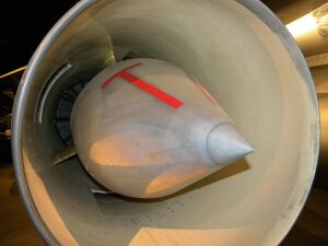 Convair B-58 Hustler early Mach 2 supersonic inlet with a centre (translating) cone which has different axial positions (5 inch travel) to reduce total pressure loss over the range of flight Mn. An oblique shock from the cone tip and a normal shock form at supersonic speeds.
 -
 Increasing loss with Mn is lessened with more shocks (urti).
 -
![A view of the entry to an SR71 Mach 3.2 mixed external-internal inlet looking in direction of airflow to the engine. The centre translating cone has 26 inches of travel between extended, up to M1.6 (shown), and fully retracted at M3.2. An oblique shock from the cone tip, an internal oblique shock from the cowl lip and a normal shock[103] give the required pressure recovery at M3.2. The boundary layers on the cone and cowl inner surface have to be removed before the final shock-wave where the flow becomes subsonic. Otherwise shock-induced separation occurs. The two removal features are just visible. The cone boundary layer is removed through the band of holes (porous bleed). The boundary layer on the cowl inner surface is removed through a shock-trap[104] bleed. This ram bleed is just visible on the lower surface in front of a row of streamlined lumps called "mice" which reduce the rate of diffusion.[105]](/wiki/images/thumb/a/a0/Lockheed_SR-71A_Blackbird_at_Evergreen_Aviation_%26_Space_Museum_%286586637283%29.jpg/338px-Lockheed_SR-71A_Blackbird_at_Evergreen_Aviation_%26_Space_Museum_%286586637283%29.jpg) A view of the entry to an SR71 Mach 3.2 mixed external-internal inlet looking in direction of airflow to the engine. The centre translating cone has 26 inches of travel between extended, up to M1.6 (shown), and fully retracted at M3.2. An oblique shock from the cone tip, an internal oblique shock from the cowl lip and a normal shock[103] give the required pressure recovery at M3.2. The boundary layers on the cone and cowl inner surface have to be removed before the final shock-wave where the flow becomes subsonic. Otherwise shock-induced separation occurs. The two removal features are just visible. The cone boundary layer is removed through the band of holes (porous bleed). The boundary layer on the cowl inner surface is removed through a shock-trap[104] bleed. This ram bleed is just visible on the lower surface in front of a row of streamlined lumps called "mice" which reduce the rate of diffusion.[105]
A view of the entry to an SR71 Mach 3.2 mixed external-internal inlet looking in direction of airflow to the engine. The centre translating cone has 26 inches of travel between extended, up to M1.6 (shown), and fully retracted at M3.2. An oblique shock from the cone tip, an internal oblique shock from the cowl lip and a normal shock[103] give the required pressure recovery at M3.2. The boundary layers on the cone and cowl inner surface have to be removed before the final shock-wave where the flow becomes subsonic. Otherwise shock-induced separation occurs. The two removal features are just visible. The cone boundary layer is removed through the band of holes (porous bleed). The boundary layer on the cowl inner surface is removed through a shock-trap[104] bleed. This ram bleed is just visible on the lower surface in front of a row of streamlined lumps called "mice" which reduce the rate of diffusion.[105] -
 Shock waves on a mixed external/internal inlet, as used on the Lockheed SR-71 Blackbird. The image on the right shows the inlet operating correctly with minimum pressure loss. It has 2 shockwaves, the first is visible originating at the tip of the cone and the second which results from the flow slowing from supersonic to subsonic speed is not visible as it is positioned inside the inlet. The inlet is called an external/internal or mixed compression inlet as some supersonic diffusion takes place inside the duct. The left image shows the inlet operating with excessive loss in total pressure as the internal terminal shock has been pushed forward out of the inlet.
_(2).jpg)

![A view of the entry to an SR71 Mach 3.2 mixed external-internal inlet looking in direction of airflow to the engine. The centre translating cone has 26 inches of travel between extended, up to M1.6 (shown), and fully retracted at M3.2. An oblique shock from the cone tip, an internal oblique shock from the cowl lip and a normal shock[103] give the required pressure recovery at M3.2. The boundary layers on the cone and cowl inner surface have to be removed before the final shock-wave where the flow becomes subsonic. Otherwise shock-induced separation occurs. The two removal features are just visible. The cone boundary layer is removed through the band of holes (porous bleed). The boundary layer on the cowl inner surface is removed through a shock-trap[104] bleed. This ram bleed is just visible on the lower surface in front of a row of streamlined lumps called "mice" which reduce the rate of diffusion.[105]](/wiki/File:Lockheed_SR-71A_Blackbird_at_Evergreen_Aviation_%26_Space_Museum_(6586637283).jpg)

Flow through bypass ducts is subject to frictional losses and obstructions causing flow separation. Care has to be taken to avoid steps and gaps which increase flow losses as does their presence on aircraft surfaces where they cause drag.[106] Ducts need internal streamlining in the same way as external surfaces. Tubes have to cross the duct bringing compressed air from the gas generator to the aircraft pylon for its ECS. The tubes creates turbulent wakes in the bypass air which shows up as a pressure loss, an increase in entropy. A streamlined fairing round the tube is a performance improvement, it reduces the rise in entropy. The higher the flow Mn the greater the pressure loss.[107]
-
 Pratt & Whitney TF30. Early military bypass engine showing two bleed air tubes obstructing airflow in bypass duct
 -
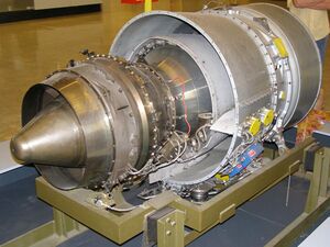 Pratt & Whitney Canada PW500 PW305 business jet turbofan showing fairing around bleed air tubes to reduce bypass duct pressure loss
 -
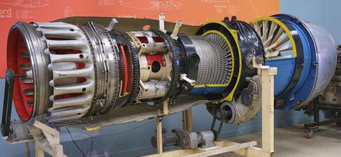 Rolls-Royce Spey early civil bypass engine. White fuel tubes, one for each flame can, only 3 shown, have cast streamlined outer profile where they cross the bypass airflow.
 -
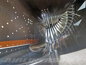 Airbus A380 engine. The smooth bypass duct interior minimizes flow losses. Gaps have to be filled with grey sealer and misalignment of parts is also evident.


In constant area ducts (jetpipe) and constant area ducts with heat addition (engine combustor and afterburner) the gas accelerates due to heating up with wall friction (duct), obstructions (flame tube, flameholders and fuel manifolds), and heat addition. It accelerates subsonically, with increasing pressure loss, towards the speed of sound. To keep the pressure loss to an acceptable value the flow entering the duct is slowed down using an increase in flow area.
-
![Power Jets W.2 for its initial installation in the Gloster E28/39 was tested with no diffusion from the turbine exit Mn of 0.8. The turbine blade annulus area was used for the length of pipe necessary to reach the tail of the aircraft. The exhaust reached the speed of sound at a low thrust but at the turbine temperature limit due to the excessive pressure loss and frictional heating. Diffusion was added behind the turbine with the cone shown to reduce the pipe entry Mach number.[108]](/wiki/images/thumb/e/ea/Power_jets_W.2.jpg/300px-Power_jets_W.2.jpg) Power Jets W.2 for its initial installation in the Gloster E28/39 was tested with no diffusion from the turbine exit Mn of 0.8. The turbine blade annulus area was used for the length of pipe necessary to reach the tail of the aircraft. The exhaust reached the speed of sound at a low thrust but at the turbine temperature limit due to the excessive pressure loss and frictional heating. Diffusion was added behind the turbine with the cone shown to reduce the pipe entry Mach number.[108]
Power Jets W.2 for its initial installation in the Gloster E28/39 was tested with no diffusion from the turbine exit Mn of 0.8. The turbine blade annulus area was used for the length of pipe necessary to reach the tail of the aircraft. The exhaust reached the speed of sound at a low thrust but at the turbine temperature limit due to the excessive pressure loss and frictional heating. Diffusion was added behind the turbine with the cone shown to reduce the pipe entry Mach number.[108] -
Turbojet with afterburner. The exhaust has to be at a low enough Mn before heat addition to prevent excessive pressure loss. A diffuser is added to reduce the Mn at the beginning of the combustion zone. The afterburner then converges to match the nozzle size.
![Power Jets W.2 for its initial installation in the Gloster E28/39 was tested with no diffusion from the turbine exit Mn of 0.8. The turbine blade annulus area was used for the length of pipe necessary to reach the tail of the aircraft. The exhaust reached the speed of sound at a low thrust but at the turbine temperature limit due to the excessive pressure loss and frictional heating. Diffusion was added behind the turbine with the cone shown to reduce the pipe entry Mach number.[108]](/wiki/File:Power_jets_W.2.jpg)
Leakage control
The jet engine has many sealing locations, more than fifty in a large engine. The cumulative effect of leakage on fuel consumption can be significant. Gas path sealing affects engine efficiency and became increasingly more important as higher pressure compressors were introduced.[109]
There are unwanted leaks from the primary gas path and necessary bleeds from the compressor which enter the secondary or internal flow system. They are all controlled by seals with design clearances. When seals rub and wear, opening up clearances, there is performance deterioration (increased fuel consumption).
Sealing of the stators was initially accomplished using knife-edge fins on the rotating part and a smooth surface for the stator shroud. Examples are the Avon and Tumansky R-11. With the invention of the honeycomb seal the labyrinth seal has an abrasive honeycomb shroud which is easily cut by the rotating seal teeth without overheating and damaging them.[110] Labyrinth seals are also used in the secondary air system between rotating and stationary parts. Example locations for these are shown by Bobo.[111] Tip clearance between compressor and turbine blades[112] and their cases is a significant source of performance loss. Much of the loss in compressors is associated with tip clearance flow.[113] For a CFM56 engine an increase in high pressure turbine tip clearance of 0.25 mm causes the engine to run 10 °C hotter (reduced efficiency) to attain take off thrust.[114] Tip clearances have to be big enough to prevent rubbing when they tend to close up during carcase bending, case distortion from thrust transfer, centre-line closure when the compressor case shrinks onto the rotor diameter (rapid reduction in temperature of air entering the engine), thrust setting changes (controlled by Active Clearance Control using compressor rotor cooling and turbine case cooling).
-
Tumansky R-11 shrouded vane interstage labyrinth, (knife/teeth) on rotor, seal visible between LP stage 2 and 3[115]
-
Pratt & Whitney TF30. Early military bypass engine showing compressor discharge six-fin labyrinth seal [116]
-
![Turbomeca Marboré IV engine showing location of leakage between impeller blades and stationary shroud, shown sectioned and painted blue. This is the leak path for a centrifugal impeller equivalent to an axial blade tip to casing clearance.[117]](/wiki/images/thumb/8/88/Marbore_IV.jpg/300px-Marbore_IV.jpg) Turbomeca Marboré IV engine showing location of leakage between impeller blades and stationary shroud, shown sectioned and painted blue. This is the leak path for a centrifugal impeller equivalent to an axial blade tip to casing clearance.[117]
Turbomeca Marboré IV engine showing location of leakage between impeller blades and stationary shroud, shown sectioned and painted blue. This is the leak path for a centrifugal impeller equivalent to an axial blade tip to casing clearance.[117] -
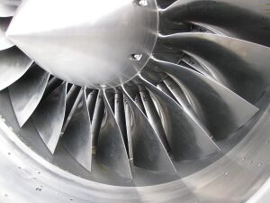 EJ200 fan showing clearance between blade tips and abradable shroud.
 -
![Turbine blades with sealing shroud at tip with knife edge fins which are part of the labyrinth sealing arrangement with open honeycomb shrouds on the turbine casing.[118] The platforms at the base of the airfoil stops hot gas leakage which would overheat the turbine discs.](/wiki/images/thumb/c/ce/2013-09-18_TrentTurbineBlades.jpg/326px-2013-09-18_TrentTurbineBlades.jpg) Turbine blades with sealing shroud at tip with knife edge fins which are part of the labyrinth sealing arrangement with open honeycomb shrouds on the turbine casing.[118] The platforms at the base of the airfoil stops hot gas leakage which would overheat the turbine discs.
Turbine blades with sealing shroud at tip with knife edge fins which are part of the labyrinth sealing arrangement with open honeycomb shrouds on the turbine casing.[118] The platforms at the base of the airfoil stops hot gas leakage which would overheat the turbine discs.
![Turbomeca Marboré IV engine showing location of leakage between impeller blades and stationary shroud, shown sectioned and painted blue. This is the leak path for a centrifugal impeller equivalent to an axial blade tip to casing clearance.[117]](/wiki/File:Marbore_IV.jpg)

![Turbine blades with sealing shroud at tip with knife edge fins which are part of the labyrinth sealing arrangement with open honeycomb shrouds on the turbine casing.[118] The platforms at the base of the airfoil stops hot gas leakage which would overheat the turbine discs.](/wiki/File:2013-09-18_TrentTurbineBlades.jpg)
Tip clearance changes with thrust changes
An engine is designed to run steady state at design points such as take-off, climb, and cruise with running clearances which minimize fuel use. Steady state means being at a constant rpm for long enough (several minutes) for all parts to have stopped moving relative to each other from transient thermal growths. During this time clearances between parts may close up to rubbing contact and wear to give larger clearances, and fuel consumption, at the important stabilized condition. This scenario inside the engine is prevented by internal compressor bore cooling[119] and external turbine casing cooling on big fan engines (active clearance control). [120][121][122]
-
![This rear view of a Klimov VK-1 turbojet shows the parts responsible for turbine temperature overshoot after increasing thrust from idle to take-off, known as transient EGT overshoot.[123] Visible is the turbine blade tip clearance which is a leakage path for gas which doesn't contribute to the power developed by the turbine. Increased gap, and leakage, means more fuel, indicated by a higher EGT, is required to get take-off thrust. Clearance is increased temporarily every time the engine goes from idle to take-off because the light casing expands quickly to the turbine gas temperature but the heavy turbine rotor takes minutes to expand to its hot diameter.](/wiki/images/thumb/a/ac/WSK_Lis-5_PM_MWB_02.jpg/300px-WSK_Lis-5_PM_MWB_02.jpg) This rear view of a Klimov VK-1 turbojet shows the parts responsible for turbine temperature overshoot after increasing thrust from idle to take-off, known as transient EGT overshoot.[123] Visible is the turbine blade tip clearance which is a leakage path for gas which doesn't contribute to the power developed by the turbine. Increased gap, and leakage, means more fuel, indicated by a higher EGT, is required to get take-off thrust. Clearance is increased temporarily every time the engine goes from idle to take-off because the light casing expands quickly to the turbine gas temperature but the heavy turbine rotor takes minutes to expand to its hot diameter.
This rear view of a Klimov VK-1 turbojet shows the parts responsible for turbine temperature overshoot after increasing thrust from idle to take-off, known as transient EGT overshoot.[123] Visible is the turbine blade tip clearance which is a leakage path for gas which doesn't contribute to the power developed by the turbine. Increased gap, and leakage, means more fuel, indicated by a higher EGT, is required to get take-off thrust. Clearance is increased temporarily every time the engine goes from idle to take-off because the light casing expands quickly to the turbine gas temperature but the heavy turbine rotor takes minutes to expand to its hot diameter. -
![This view shows the way turbine blade tip clearance is controlled actively (passive control is by material selection and internal air system cooling) using cooling-air tubes (for low pressure turbine blade tip to shroud clearance control) which circle the iridescent turbine casing on a CFM International CFM56. Cooling air manifold (smooth flat surface), to left of LPTCC tubes, for high pressure turbine blade tip clearance control.[124] Active control comes from activation of valves which supply cooling air to the tubes at appropriate flight conditions.](/wiki/images/thumb/6/6e/CFM_International_CFM56-7B26_fitted_to_Qantas_%28VH-VZY%29_Boeing_737-838_%28WL%29_at_the_Canberra_Airport_open_day_%285%29.jpg/338px-CFM_International_CFM56-7B26_fitted_to_Qantas_%28VH-VZY%29_Boeing_737-838_%28WL%29_at_the_Canberra_Airport_open_day_%285%29.jpg) This view shows the way turbine blade tip clearance is controlled actively (passive control is by material selection and internal air system cooling) using cooling-air tubes (for low pressure turbine blade tip to shroud clearance control) which circle the iridescent turbine casing on a CFM International CFM56. Cooling air manifold (smooth flat surface), to left of LPTCC tubes, for high pressure turbine blade tip clearance control.[124] Active control comes from activation of valves which supply cooling air to the tubes at appropriate flight conditions.
This view shows the way turbine blade tip clearance is controlled actively (passive control is by material selection and internal air system cooling) using cooling-air tubes (for low pressure turbine blade tip to shroud clearance control) which circle the iridescent turbine casing on a CFM International CFM56. Cooling air manifold (smooth flat surface), to left of LPTCC tubes, for high pressure turbine blade tip clearance control.[124] Active control comes from activation of valves which supply cooling air to the tubes at appropriate flight conditions.
![This rear view of a Klimov VK-1 turbojet shows the parts responsible for turbine temperature overshoot after increasing thrust from idle to take-off, known as transient EGT overshoot.[123] Visible is the turbine blade tip clearance which is a leakage path for gas which doesn't contribute to the power developed by the turbine. Increased gap, and leakage, means more fuel, indicated by a higher EGT, is required to get take-off thrust. Clearance is increased temporarily every time the engine goes from idle to take-off because the light casing expands quickly to the turbine gas temperature but the heavy turbine rotor takes minutes to expand to its hot diameter.](/wiki/File:WSK_Lis-5_PM_MWB_02.jpg)
![This view shows the way turbine blade tip clearance is controlled actively (passive control is by material selection and internal air system cooling) using cooling-air tubes (for low pressure turbine blade tip to shroud clearance control) which circle the iridescent turbine casing on a CFM International CFM56. Cooling air manifold (smooth flat surface), to left of LPTCC tubes, for high pressure turbine blade tip clearance control.[124] Active control comes from activation of valves which supply cooling air to the tubes at appropriate flight conditions.](/wiki/File:CFM_International_CFM56-7B26_fitted_to_Qantas_(VH-VZY)_Boeing_737-838_(WL)_at_the_Canberra_Airport_open_day_(5).jpg)
Sealing at blade tips and stator shrouds
In the late 1940s it was considered by most US engine manufacturers that the optimum pr was 6:1 in light of the amount of leakage flow expected with the then-current sealing knowledge. P&W considered 12:1 could be achieved[125] but during pre-J57 development testing a compressor with 8:1 was tested and the leakage was so high that no useful work would have been produced.[126] One benefit of the subsequent wasp waist was reduced leakage from the reduced sealing diameter. In 1954 a GE engineer invented a very effective sealing scheme, the honeycomb seal[127] which reduces substantially the rubbing contact area and temperatures generated. The rotating part cuts into the cellular structure without being permanently damaged. It is widely used today. The primary gas flow through the compressor and turbine has to follow the airfoil surfaces to exchange energy with the turbomachinery. Any flow leaking past the blade tips generates entropy and reduces the efficiency of the compressor and turbine. Interlocking shrouds are present on the tips of low pressure turbine blades to provide an outer band to the flowpath which reduces tip leakage. Leakage is further reduced with the addition of seal teeth on the outer periphery of the shrouds which rub into open cell honeycomb shrouds.
-
Avon compressor shrouded vane interstage seals with labyrinth teeth on rotor
-
LPT blade interlocking tip shrouds with seal teeth which rub into open-cell honeycomb shrouds
-
 v2500 compressor showing seal teeth between blade rows.
 -
 Open-cell honeycomb on the shrouds at the stator/compressor drum interface showing grooves cut by mating seal teeth on rotating drum.
 -
 TFE 731 geared turbofan abradable locations in compressor and turbines
 -
 CFM International CFM56-2 shows fan tip shrouds which prevent circulation of air around the blade ends.
.JPG)


.jpg)
Tip clearance with backbone bending and case out-of-roundness
The advent of the high bypass civil engines, JT9D and CF6, showed the importance of thrust take off locations on the engine cases. Also, large engines have relatively flexible cases inherent in large diameter flight-weight structures giving relatively large relative displacements between heavy stiff rotors and the flexible cases.[128] Case distortion with subsequent blade tip rubbing and performance loss appeared on the JT9D installation in the Boeing 747 as a result of thrust being taken from a single point on top of the engine exhaust case. Thrust from the rear mount plane was a Boeing requirement.[129] Compared to the 15,000 lb thrust JT3D with its four structural cases the 40,000 lb thrust JT9D made economical use of supporting structure with only three structural cases making a compact lightweight design.[130] During flight testing the engines suffered violent surges and loss in performance[131] which were traced to bending of the engine backbone by 0.043 in. at the combustor case and the turbine case going out-of-round which in turn caused blade tip rubs and increased tip clearance.[132]
The three big fan engines introduced in the 1960s for wide-body airliners, Boeing 747, Lockheed Tristar, DC-10, had much higher thrust and size compared to the engines powering the previous generation of airliners. The JT9D and CF6 showed that rotor tip clearances were sensitive to the way the engines were mounted and performance was lost through rotor tip rubs due to backbone bending and local distortion of casings at the point of thrust transfer to the aircraft pylon.[133] At the same time the RB211 performance didn't deteriorate so fast due to its shorter, more rigid, three-shaft configuration. For the Boeing 777[134][135] the Trent 800[136] and GE90 would incorporate two-point mounting for ovalization reduction.[137]
The first high bypass fan engine, the TF39, transferred its thrust to the C5 pylon from the rear mount. It was a single point thrust location on the turbine mid-frame which locally distorted the casings, causing out of roundness of the turbine stators, increased clearances and a performance loss. The CF6-6, derived from the TF39 had thrust taken for the DC-10 from the front mount plane but also from a single point. This also caused single point distortion and unacceptable performance loss for the airliner. The distortion was reduced by taking thrust from two points which allowed smaller compressor running clearances and better SFC.
-
 Under normal conditions the most severe air loading on the engine carcase is at take-off when the high mass flow at take-off thrust combines with a high angle of attack meaning a large momentum change, and force, is required to align the airflow with the engine.
 -
![General Electric CF6-6 engine. Aerodynamic loads on the inlet cowl (left) are highest at high angles of attack during take-off rotation and climb. The air approaching from below[138] has to turn into the engine inlet and the force required to change its momentum is reacted as an upwards force on a CF6-50 inlet of about 4 tons.[139] The inlet is bolted to the fan case and the bending moment is transferred inwardly through the struts shown into the core casing.](/wiki/images/thumb/5/5f/General_Electric_GE_CF6-6_High-bypass_turbofan_engine_-_NARA_-_17447451_%28cropped%29.jpg/492px-General_Electric_GE_CF6-6_High-bypass_turbofan_engine_-_NARA_-_17447451_%28cropped%29.jpg) General Electric CF6-6 engine. Aerodynamic loads on the inlet cowl (left) are highest at high angles of attack during take-off rotation and climb. The air approaching from below[138] has to turn into the engine inlet and the force required to change its momentum is reacted as an upwards force on a CF6-50 inlet of about 4 tons.[139] The inlet is bolted to the fan case and the bending moment is transferred inwardly through the struts shown into the core casing.
General Electric CF6-6 engine. Aerodynamic loads on the inlet cowl (left) are highest at high angles of attack during take-off rotation and climb. The air approaching from below[138] has to turn into the engine inlet and the force required to change its momentum is reacted as an upwards force on a CF6-50 inlet of about 4 tons.[139] The inlet is bolted to the fan case and the bending moment is transferred inwardly through the struts shown into the core casing. -
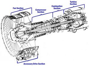 CF6 struts linking the fan case to the compressor case transfer the air loads from the inlet to the engine backbone, causing bending, case distortion and blade tip rubs. Clearances have to be increased to prevent rubs and performance is lost.

![General Electric CF6-6 engine. Aerodynamic loads on the inlet cowl (left) are highest at high angles of attack during take-off rotation and climb. The air approaching from below[138] has to turn into the engine inlet and the force required to change its momentum is reacted as an upwards force on a CF6-50 inlet of about 4 tons.[139] The inlet is bolted to the fan case and the bending moment is transferred inwardly through the struts shown into the core casing.](/wiki/File:General_Electric_GE_CF6-6_High-bypass_turbofan_engine_-_NARA_-_17447451_(cropped).jpg)

-
![The Pratt & Whitney JT3D is an example of an early turbofan engine. These engines typically encountered bending along the length of the engine and localised out of roundness where the thrust was transferred from the engine. These issues caused no real concern because thrust levels which caused the distortions were low enough and blade clearances were large enough.[140]](/wiki/images/thumb/0/09/American_Airlines_C.R._Smith_Museum_May_2019_17_%28Pratt_%26_Whitney_JT3D%29.jpg/338px-American_Airlines_C.R._Smith_Museum_May_2019_17_%28Pratt_%26_Whitney_JT3D%29.jpg) The Pratt & Whitney JT3D is an example of an early turbofan engine. These engines typically encountered bending along the length of the engine and localised out of roundness where the thrust was transferred from the engine. These issues caused no real concern because thrust levels which caused the distortions were low enough and blade clearances were large enough.[140]
The Pratt & Whitney JT3D is an example of an early turbofan engine. These engines typically encountered bending along the length of the engine and localised out of roundness where the thrust was transferred from the engine. These issues caused no real concern because thrust levels which caused the distortions were low enough and blade clearances were large enough.[140] -
![A Pratt & Whitney JT9D museum exhibit with none of the accessories, tubes, wiring and cowls which cover a functional engine. Revealed are the casings bolted together which make up the structural backbone of the engine.[141] The engine thrust is transferred to the aircraft pylon at the top of the turbine case. As this is above the engine centerline where the thrust acts it causes backbone bending in the core engine[142] which in turn causes blade tip rubs and performance loss.](/wiki/images/thumb/1/1a/JT9D_on_747.JPG/300px-JT9D_on_747.JPG) A Pratt & Whitney JT9D museum exhibit with none of the accessories, tubes, wiring and cowls which cover a functional engine. Revealed are the casings bolted together which make up the structural backbone of the engine.[141] The engine thrust is transferred to the aircraft pylon at the top of the turbine case. As this is above the engine centerline where the thrust acts it causes backbone bending in the core engine[142] which in turn causes blade tip rubs and performance loss.
A Pratt & Whitney JT9D museum exhibit with none of the accessories, tubes, wiring and cowls which cover a functional engine. Revealed are the casings bolted together which make up the structural backbone of the engine.[141] The engine thrust is transferred to the aircraft pylon at the top of the turbine case. As this is above the engine centerline where the thrust acts it causes backbone bending in the core engine[142] which in turn causes blade tip rubs and performance loss. -
![General Electric GE90 shows one of two locations (45 degrees either side of top centre) on fan frame where engine thrust is transferred by links to the rear thrust mount for transfer to the aircraft pylon.[135]](/wiki/images/thumb/a/aa/2016.10.13.111932_Detail_GE90_jet_engine_Future_of_Flight_Center_%26_Boeing_Tour_Everett_Washington.jpg/338px-2016.10.13.111932_Detail_GE90_jet_engine_Future_of_Flight_Center_%26_Boeing_Tour_Everett_Washington.jpg) General Electric GE90 shows one of two locations (45 degrees either side of top centre) on fan frame where engine thrust is transferred by links to the rear thrust mount for transfer to the aircraft pylon.[135]
General Electric GE90 shows one of two locations (45 degrees either side of top centre) on fan frame where engine thrust is transferred by links to the rear thrust mount for transfer to the aircraft pylon.[135] -
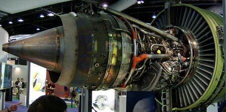 GE90 shows one of two thrust links to the rear thrust mount on the exhaust case. Early JT9D and CF6 engines had thrust transferred from a single location on the top of the engine backbone which distorted the casing requiring increased tip clearances to prevent rubs. Acceptable distortion, with smaller tip clearances, was obtained if thrust was shared between 2 locations, one either side of vertical. This is common on modern engines of this type.
 -
 Trent 900 thrust loads are transferred from the engine through 2 thrust links (shown with orange maintenance protective sleeves) connected to the engine rear mount and wing pylon.
![The Pratt & Whitney JT3D is an example of an early turbofan engine. These engines typically encountered bending along the length of the engine and localised out of roundness where the thrust was transferred from the engine. These issues caused no real concern because thrust levels which caused the distortions were low enough and blade clearances were large enough.[140]](/wiki/File:American_Airlines_C.R._Smith_Museum_May_2019_17_(Pratt_%26_Whitney_JT3D).jpg)
![A Pratt & Whitney JT9D museum exhibit with none of the accessories, tubes, wiring and cowls which cover a functional engine. Revealed are the casings bolted together which make up the structural backbone of the engine.[141] The engine thrust is transferred to the aircraft pylon at the top of the turbine case. As this is above the engine centerline where the thrust acts it causes backbone bending in the core engine[142] which in turn causes blade tip rubs and performance loss.](/wiki/File:JT9D_on_747.JPG)
![General Electric GE90 shows one of two locations (45 degrees either side of top centre) on fan frame where engine thrust is transferred by links to the rear thrust mount for transfer to the aircraft pylon.[135]](/wiki/File:2016.10.13.111932_Detail_GE90_jet_engine_Future_of_Flight_Center_%26_Boeing_Tour_Everett_Washington.jpg)

.JPG)
Internal or secondary air system
The use of air for internal systems increases fuel consumption so there is a need to minimize the airflow required. The internal air system uses secondary air for cooling, keeping oil in bearing chambers, to control bearing thrust load for bearing life, and preventing hot gas ingestion from turbine gas flow into disc cavities. It is a cooling system which uses airflow to transfer heat away from hot parts and maintain them at a temperature which ensures the life of parts such as turbine discs and blades. It is also a purge system which uses air to pressurize cavities to prevent hot flowpath gas from entering and overheating disc rims where blades are attached. It is used to cool or heat parts to control radial clearances (clearance control system). Early radial compressor engines used supplementary means for cooling air, for example a dedicated impeller or a fan machined integral with the turbine disc. The air sources for axial engines are different stages along the compressor depending on the different air system pressure requirements. Use of a single stage impeller as the last high pressure stage on small turbofan engines gives the flexibility of three different source pressures from the single stage, impeller entry, halfway through the stage (impeller tip) and diffuser exit (at combustor pressure). The air system sinks are the primary gas path where turbine cooling air is returned, for example, and the oil system vent overboard.
-
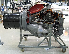 Pratt & Whitney J42 shows secondary air system impeller for bearing cooling air.
 -
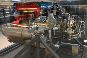 General Electric J31 secondary air fan blades integral with turbine disc for disc cooling.
 -
de Havilland Ghost shows labyrinth teeth on the impeller backface to reduce air loss from the impeller and control the pressure on the back face. The radial position of the seal is chosen to set the area on which the pressure acts so the forward thrust on the impeller substantially balances the rearward thrust from the turbine which reduces the axial force on the rotor thrust bearing.[143]
-
Rolls-Royce Turbomeca Adour labyrinth seals with honeycomb shrouds on turbine discs. The one visible to the left reduces leakage between the two turbine stages. The one visible to the right reduces leaks from the combustor high pressure gas needed by the turbine.
-
![Adour labyrinth seal with 3 fins on the blade platforms and a honeycomb shroud is a type of rim seal to prevent hot gas ingestion at the turbine disc rim.[144]](/wiki/images/thumb/7/7e/Turbine_of_a_sectioned_Rolls-Royce_Turbom%C3%A9ca_Adour_turbofan.jpg/338px-Turbine_of_a_sectioned_Rolls-Royce_Turbom%C3%A9ca_Adour_turbofan.jpg) Adour labyrinth seal with 3 fins on the blade platforms and a honeycomb shroud is a type of rim seal to prevent hot gas ingestion at the turbine disc rim.[144]
Adour labyrinth seal with 3 fins on the blade platforms and a honeycomb shroud is a type of rim seal to prevent hot gas ingestion at the turbine disc rim.[144] -
![CFM56 showing internal air system overboard vent for the oil system (vent tube in the exhaust). Secondary air enters the bearing compartments through labyrinth seals to prevent oil escaping in the opposite direction. The air continually escapes from the system through the vent with some oil mist after passing through a centrifugal air/oil separator.[145]](/wiki/images/thumb/e/e3/CFM_International_CFM56-7B26_fitted_to_Qantas_%28VH-VZY%29_Boeing_737-838_%28WL%29_at_the_Canberra_Airport_open_day.jpg/338px-CFM_International_CFM56-7B26_fitted_to_Qantas_%28VH-VZY%29_Boeing_737-838_%28WL%29_at_the_Canberra_Airport_open_day.jpg) CFM56 showing internal air system overboard vent for the oil system (vent tube in the exhaust). Secondary air enters the bearing compartments through labyrinth seals to prevent oil escaping in the opposite direction. The air continually escapes from the system through the vent with some oil mist after passing through a centrifugal air/oil separator.[145]
CFM56 showing internal air system overboard vent for the oil system (vent tube in the exhaust). Secondary air enters the bearing compartments through labyrinth seals to prevent oil escaping in the opposite direction. The air continually escapes from the system through the vent with some oil mist after passing through a centrifugal air/oil separator.[145]


![Adour labyrinth seal with 3 fins on the blade platforms and a honeycomb shroud is a type of rim seal to prevent hot gas ingestion at the turbine disc rim.[144]](/wiki/File:Turbine_of_a_sectioned_Rolls-Royce_Turbom%C3%A9ca_Adour_turbofan.jpg)
![CFM56 showing internal air system overboard vent for the oil system (vent tube in the exhaust). Secondary air enters the bearing compartments through labyrinth seals to prevent oil escaping in the opposite direction. The air continually escapes from the system through the vent with some oil mist after passing through a centrifugal air/oil separator.[145]](/wiki/File:CFM_International_CFM56-7B26_fitted_to_Qantas_(VH-VZY)_Boeing_737-838_(WL)_at_the_Canberra_Airport_open_day.jpg)
Performance deterioration
Gas path deterioration and increasing EGT coexist. As the gas path deteriorates the EGT limit ultimately prevents the take-off thrust from being achieved and the engine has to be repaired.[146] The engine performance deteriorates with use as parts wear, meaning the engine has to use more fuel to get the required thrust. A new engine starts with a reserve of performance which is gradually eroded. The reserve is known as its temperature margin and is seen by a pilot as the EGT margin. For a new CFM International CFM56-3 the margin is 53 °C.[147][43] Kraus[148] gives the effect on increased fuel consumption of typical component degradation during service.
-
![The Pratt & Whitney JT8D has a full length fan duct which is a rigid case construction which resists inlet air loads during aircraft rotation. Compared to the later JT9D it has relatively loose clearances between rotating and stationary parts so blade tip rubs as a source of performance deterioration were not an issue.[149]](/wiki/images/thumb/2/23/Pratt_%26_Whitney_JT8D-17A_1.JPG/342px-Pratt_%26_Whitney_JT8D-17A_1.JPG) The Pratt & Whitney JT8D has a full length fan duct which is a rigid case construction which resists inlet air loads during aircraft rotation. Compared to the later JT9D it has relatively loose clearances between rotating and stationary parts so blade tip rubs as a source of performance deterioration were not an issue.[149]
The Pratt & Whitney JT8D has a full length fan duct which is a rigid case construction which resists inlet air loads during aircraft rotation. Compared to the later JT9D it has relatively loose clearances between rotating and stationary parts so blade tip rubs as a source of performance deterioration were not an issue.[149] -
![The Pratt & Whitney JT9D with a big increase in thrust over the JT8D raised awareness how to transfer engine thrust to the aircraft without bending the engine too much and causing rubs and performance deterioration.[150]](/wiki/images/thumb/a/a7/P%26W_JT9D_cutaway.jpg/337px-P%26W_JT9D_cutaway.jpg) The Pratt & Whitney JT9D with a big increase in thrust over the JT8D raised awareness how to transfer engine thrust to the aircraft without bending the engine too much and causing rubs and performance deterioration.[150]
The Pratt & Whitney JT9D with a big increase in thrust over the JT8D raised awareness how to transfer engine thrust to the aircraft without bending the engine too much and causing rubs and performance deterioration.[150] -
 Klimov VK-1 centrifugal impeller showing that the blades have rubbed on the shroud causing increased clearance and leakage losses.
 -
Turbomeca Marboré IV engine showing location of leakage between impeller blades and stationary shroud, shown sectioned and painted blue. This is the leak path for a centrifugal impeller equivalent to an axial blade tip to casing clearance.[117] The clearance between the impeller vanes and their shroud is visible and has to be as small as possible without causing rubbing contact. This keeps leakage to a minimum and contributes to the efficiency of the engine.
-
An example of the appearance of minor compressor blade tip rubs on their shrouds.
-
![A used CFM56 high pressure turbine blade. New blades have 3 different-depth notches at the tip to aid visual assessment (using a borescope) of rubbed away material and consequent increase in tip clearance. 0.25 mm of lost blade-tip causes a 10 deg C loss of EGT margin.[151]](/wiki/images/thumb/a/a1/CFM56_High_Pressure_Turbine_Blade.JPG/300px-CFM56_High_Pressure_Turbine_Blade.JPG) A used CFM56 high pressure turbine blade. New blades have 3 different-depth notches at the tip to aid visual assessment (using a borescope) of rubbed away material and consequent increase in tip clearance. 0.25 mm of lost blade-tip causes a 10 deg C loss of EGT margin.[151]
A used CFM56 high pressure turbine blade. New blades have 3 different-depth notches at the tip to aid visual assessment (using a borescope) of rubbed away material and consequent increase in tip clearance. 0.25 mm of lost blade-tip causes a 10 deg C loss of EGT margin.[151] -
![CFM56 turbine nozzle guide vanes. The area for the combustor gas flow for the complete ring of vanes at the narrowest part of the passage is known as the turbine area. When the vane trailing edges deteriorate the area increases and the engine runs hotter, which causes increasingly rapid deterioration, and uses more fuel to reach take-off thrust.[152]](/wiki/images/thumb/b/b7/CFM56_High_Pressure_Turbine_Vane.JPG/300px-CFM56_High_Pressure_Turbine_Vane.JPG) CFM56 turbine nozzle guide vanes. The area for the combustor gas flow for the complete ring of vanes at the narrowest part of the passage is known as the turbine area. When the vane trailing edges deteriorate the area increases and the engine runs hotter, which causes increasingly rapid deterioration, and uses more fuel to reach take-off thrust.[152]
CFM56 turbine nozzle guide vanes. The area for the combustor gas flow for the complete ring of vanes at the narrowest part of the passage is known as the turbine area. When the vane trailing edges deteriorate the area increases and the engine runs hotter, which causes increasingly rapid deterioration, and uses more fuel to reach take-off thrust.[152] -
A V2500 vane showing thermal damage at the trailing edge which causes performance loss by altering the flow area.
-
![The rough turbine blade airfoil surfaces have a higher friction coefficient than smooth surfaces and cause friction drag which is a source of loss in the turbine.[153]](/wiki/images/thumb/3/38/TURBINE_BLADES_-_DPLA_-_df5b1b1c388e127aca37fc549964a38c.jpg/284px-TURBINE_BLADES_-_DPLA_-_df5b1b1c388e127aca37fc549964a38c.jpg) The rough turbine blade airfoil surfaces have a higher friction coefficient than smooth surfaces and cause friction drag which is a source of loss in the turbine.[153]
The rough turbine blade airfoil surfaces have a higher friction coefficient than smooth surfaces and cause friction drag which is a source of loss in the turbine.[153]
![The Pratt & Whitney JT8D has a full length fan duct which is a rigid case construction which resists inlet air loads during aircraft rotation. Compared to the later JT9D it has relatively loose clearances between rotating and stationary parts so blade tip rubs as a source of performance deterioration were not an issue.[149]](/wiki/File:Pratt_%26_Whitney_JT8D-17A_1.JPG)
![The Pratt & Whitney JT9D with a big increase in thrust over the JT8D raised awareness how to transfer engine thrust to the aircraft without bending the engine too much and causing rubs and performance deterioration.[150]](/wiki/File:P%26W_JT9D_cutaway.jpg)

![A used CFM56 high pressure turbine blade. New blades have 3 different-depth notches at the tip to aid visual assessment (using a borescope) of rubbed away material and consequent increase in tip clearance. 0.25 mm of lost blade-tip causes a 10 deg C loss of EGT margin.[151]](/wiki/File:CFM56_High_Pressure_Turbine_Blade.JPG)
![CFM56 turbine nozzle guide vanes. The area for the combustor gas flow for the complete ring of vanes at the narrowest part of the passage is known as the turbine area. When the vane trailing edges deteriorate the area increases and the engine runs hotter, which causes increasingly rapid deterioration, and uses more fuel to reach take-off thrust.[152]](/wiki/File:CFM56_High_Pressure_Turbine_Vane.JPG)
![The rough turbine blade airfoil surfaces have a higher friction coefficient than smooth surfaces and cause friction drag which is a source of loss in the turbine.[153]](/wiki/File:TURBINE_BLADES_-_DPLA_-_df5b1b1c388e127aca37fc549964a38c.jpg)
American Airlines experience with the JT3C turbojet included cracking and bowing of the turbine nozzle guide vanes which adversely affected the gas flow to the rotating turbine blades causing increased fuel consumption. More significant was erosion of turbine parts by hard carbon lumps which formed around the fuel nozzles and periodically breaking away and striking and eroding turbine blades and nozzle guide vanes causing loss of EGT margin.[154]
Prior to the doubling and tripling price of fuel in the early 1970s the regain of performance after deterioration was largely a by-product of maintaining engine reliability. The rising cost of fuel and a new awareness on conservation of energy led to a need to understand which type and amount of component degradation caused how much of an increase in fuel consumption.[155] Higher bypass ratio engines were shown to be more susceptible to structural deformations which caused blade tip and seal clearances to be opened up by rubs.
American Airlines conducted tests on early bypass engines to understand to what degree component wear and accumulation of atmospheric dirt affected fuel consumption. Gas path surfaces in the fan and compressor were found to be coated with deposits of dirt, salt and oil which increased surface roughness and caused performance loss.[156] A compressor wash on a particular Pratt & Whitney JT8D bypass engine reduced the fuel consumption by 110 pounds of fuel for every hour run.[157]
Clearances between rotating and stationary parts are required to prevent contact. Increasing clearances, which occur in service as a result of rubbing, reduce the thermal efficiency which shows up when the engine uses more fuel than before. An American Airlines test on a Pratt & Whitney JT3D engine found that increasing the HP turbine tip clearance by 0.031 inch caused a 0.9% increase in fuel used.[158]
The advent of the high bypass engines introduced new structural requirements necessary to prevent blade rubs and performance deterioration. Prior to this the JT8D, for example, had thrust bending deflections minimized with a long stiff one-piece fan duct which isolated the internal engine cases from aerodynamic loads. The JT8D had good performance retention with its moderate turbine temperature and stiff structure. Rigid case construction installed engine not adversely affected by axial bending loads from inlet on TO rotation. The engine had relatively large clearances between rotating and stationary components so compressor and turbine blade tip rubs were not significant and performance degradation came from distress to the hot section and compressor blade increasing roughness and erosion.[159]
Emissions
The connection between emissions and fuel consumption is the combustion inefficiency which wastes fuel. Fuel should be completely burned so all chemical energy is liberated as heat.[160] The formation of pollutants signifies that fuel has been wasted and more fuel is required to produce a particular thrust than would otherwise be.
Noise
Noise influences the social acceptability of aircraft and maximum levels measured during takeoff and approach flyover are legislated around airports. Military aircraft noise is the subject of complaints from people living near military airfields and in remote areas under the flight paths of low level training routes. Prior to the introduction into service of the first jet airliners noise was already the subject of citizen actions around airports due to unacceptable noise from the last generation of piston-engined airliners such as xxx. Forewarned early operators of jet airliners introduced their services with noise abatement takeoff procedures, Comet Caravelle,
Passenger cabin and cockpit noise in civil aircraft and cockpit noise in military aircraft has a contribution from jet engines both as engine noise and structure-borne noise originating from engine rotor out of balance.
Starting time
Starting time is the time taken from initiating the starting sequence to reaching idle speed. A CFM-56 typical start time is 45–60 seconds.[161] Starting time is a flight safety issue for airstarts because starting has to be completed before too much altitude has been lost.[162]
Weight
The weight of an engine is reflected in the weight of the aircraft and introduces some drag penalty. Extra engine weight means a heavier structure and reduces aircraft payload.[163]
Size
The size of an engine has to be established within the engine installation envelope agreed during the design of the aircraft. The thrust governs the flow area hence size of the engine. A criterion of pounds of thrust per square foot of compressor inlet is a figure of merit. The first operational turbojets in Germany had axial compressors to meet a 1939 request from the German Air Ministry to develop engines producing 410 lb/sq ft.[164]
Cost
A lower fuel consumption engine reduces airline expenditure on buying fuel for a given fuel cost. Deterioration of performance(increased fuel consumption) in service has a cumulative effect on fuel costs as the deterioration and rise in consumption is progressive. The cost of parts replacement has to be considered relative to the saving in fuel.[165]
Terminology and explanatory notes
Clarifying momentum, work, energy, power
A basic explanation for the way burning fuel results in engine thrust uses terminology like momentum, work, energy, power and rate. Correct use of the terminology may be confirmed by using the idea of fundamental units which are mass M, length L and time T, together with the idea of a dimension, i.e. power, of the fundamental unit, say L1 for distance, and in a derived unit, say speed which is distance over time, with dimensions L1 T −1[166] The object of the jet engine is to produce thrust which it does by increasing the momentum of the air passing through it. But thrust isn't caused by the change in momentum. It's caused by the rate of change in momentum. So thrust, which is a force, has to have the same dimensions as rate of change of momentum, not momentum. Efficiences may be expressed as ratios of energy rate or power which has the same dimensions.
Force dimensions are M1 L1 T−2 , momentum has dimensions M1L1 T−1 and rate of change of momentum has dimensions M1 L1T−2, ie the same as force. Work and energy are similar quantities with dimensions M1 L2T−2. Power has dimensions M1 L2T−3.[167]
References
- ↑ Gas Turbine Performance, Second Edition, Walsh and Fletcher 2004, ISBN 0 632 06434-X, Preface
- ↑ "EGT margin indicates engine health"' pp. 5–11, Safety first The Airbus Safety magazine, February 2022
- ↑ 3.0 3.1 "A Variable Cycle Engine for Subsonic Transport Applications - PDF Free Download". https://docplayer.net/140309337-A-variable-cycle-engine-for-subsonic-transport-applications.html.
- ↑ https://arc.aiaa.org/doi/abs/10.2514/1.9176?journalCode=jpp,"Ideas and Methods of Turbomachinery Aerodynamics: A Historical View", Cumpsty and Greitzer, Fig. 1
- ↑ An engine applies a thrust force to a stationary aircraft and thrust work is done on the aircraft when it moves under the influence.
- ↑ 6.0 6.1 Kurzke, Joachim; Halliwell, Ian (2018) (in en). Propulsion and Power. doi:10.1007/978-3-319-75979-1. ISBN 978-3-319-75977-7. https://link.springer.com/book/10.1007/978-3-319-75979-1.
- ↑ Hawthorne, William (1978). "Aircraft propulsion from the back room" (in en). The Aeronautical Journal 82 (807): 93–108. doi:10.1017/S0001924000090424. ISSN 0001-9240. https://www.cambridge.org/core/journals/aeronautical-journal/article/abs/aircraft-propulsion-from-the-back-room/771675086CDE0E766BE700CD6B3198E7.
- ↑ Gaffin, William O.; Lewis, John H. (1968). "Development of the High Bypass Turbofan" (in en). Annals of the New York Academy of Sciences 154 (2): 576–589. doi:10.1111/j.1749-6632.1968.tb15216.x. ISSN 0077-8923. Bibcode: 1968NYASA.154..576G. https://nyaspubs.onlinelibrary.wiley.com/doi/10.1111/j.1749-6632.1968.tb15216.x.
- ↑ The Aerothermodynamics of Aircraft Gas Turbine Engines, Oates, Editor, AFAPL-TR-78-=52, WP AFB, Ohio, pp. 1–41
- ↑ (in English) AGARD (Advisory Group for Aerospace Research and Development), Lecture Series No.136: Ramjet and Ramrocket Propulsion Systems for Missiles. https://discovery.nationalarchives.gov.uk/details/r/530c316d-1e47-4593-afd4-cf603ac01b27.
- ↑ 11.0 11.1 "Some Fundamental Aspects of Ramjet Propulsion" (in English). ARS Journal (American Institute of Aeronautics) 27 (4). April 1957. http://archive.org/details/sim_american-rocket-society-ars-journal_1957-04_27_4.
- ↑ "Supersonic Stovepipes" (in English). The Cornell Engineer (Cornell University) 16 (6): 9. March 1951. http://archive.org/details/sim_cornell-engineer_1951-03_16_6.
- ↑ "Gas Turbines And Their Problems", Hayne Constant, Todd Reference Library, Todd Publishing Group Ltd., 1948, p. 46
- ↑ Kiran Siddappaji (November 2008). Benefits of GE 90 representative turbofan through cycle analysis (Report). doi:10.13140/RG.2.2.25078.50243. https://www.researchgate.net/publication/323790787.
- ↑ Henning Struchtrup; Gwynn Elfring (June 2008). "External losses in high-bypass turbo fan air engines". International Journal of Exergy 5 (4): 400. doi:10.1504/IJEX.2008.019112. Bibcode: 2008IJExe...5..400S. https://www.researchgate.net/publication/252167474.
- ↑ 16.0 16.1 Rubert, Kennedy F. (1945-02-01) (in en). An analysis of jet-propulsion systems making direct use of the working substance of a thermodynamic cycle (Report). https://ntrs.nasa.gov/citations/19930093532.
- ↑ Smith, Trevor I.; Christensen, Warren M.; Mountcastle, Donald B.; Thompson, John R. (2015-09-23). "Identifying student difficulties with entropy, heat engines, and the Carnot cycle". Physical Review Special Topics - Physics Education Research 11 (2). doi:10.1103/PhysRevSTPER.11.020116. Bibcode: 2015PRPER..11b0116S.
- ↑ Transactions The Manchester Association of Engineers 1904, The Temperature-Entropy Diagram, Mr. G. James Wells, p. 237
- ↑ Report of the committee appointed on the 31st March, 1896, to consider and report to the Council upon the subject of the definition of a standard or standards of thermal efficiency for steam-engines ... London, the Institution. 1898. http://archive.org/details/reportcommittee05unkngoog.
- ↑ "Gas Turbine Aero-thermodynamics", Sir Frank Whittle, ISBN 0-08-026718-1, p. 2
- ↑ Cumpsty, N. A. (1997). Jet propulsion: a simple guide to the aerodynamic and thermodynamic design and performance of jet engines. Cambridge; New York: Cambridge University Press. ISBN 978-0-521-59330-4. http://archive.org/details/jetpropulsionsim0000cump.
- ↑ Entropy Generation In Turbomachinery Flows"'Denton, SAE 902011, p. 2251
- ↑ "Loss mechanisms in Turbomachines" Denton, ASME 93-GT-435, p. 4
- ↑ "Jet engine | Engineering, Design, & Functionality | Britannica" (in en). 2023-10-24. https://www.britannica.com/technology/jet-engine.
- ↑ (in English) Journal of Aircraft September-October 1966: Vol 3 Iss 5. American Institute of Aeronautics and Astronautics. September 1966. http://archive.org/details/sim_journal-of-aircraft_september-october-1966_3_5.
- ↑ 'Jet Propulsion For Airplanes', Buckingham, NACA report 159, p. 85
- ↑ Zhemchuzhin, N. A.; Levin, M. A.; Merkulov, I. A.; Naumov, V. I.; Pozhidayev, O. A.; Frolov, S. P.; Frolov, V. S. (1977-01-01). Soviet aircraft and rockets. NASA. http://archive.org/details/nasa_techdoc_19770023121.
- ↑ 28.0 28.1 Lewis, John Hiram (1976). "Propulsive efficiency from an energy utilization standpoint" (in en). Journal of Aircraft 13 (4): 299–302. doi:10.2514/3.44525. ISSN 0021-8669. https://arc.aiaa.org/doi/10.2514/3.44525.
- ↑ rayner joel (1960). heat engines. Internet Archive. http://archive.org/details/heatengines0000rayn.
- ↑ Weber, Richard J.; Mackay, John S. (1958-09-01) (in en). An Analysis of Ramjet Engines Using Supersonic Combustion (Report). https://ntrs.nasa.gov/citations/19930085282.
- ↑ 31.0 31.1 Mattingly, Jack D.; Boyer, Keith M. (2016-01-20) (in en). Elements of Propulsion: Gas Turbines and Rockets, Second Edition. Reston, VA: American Institute of Aeronautics and Astronautics, Inc.. doi:10.2514/4.103711. ISBN 978-1-62410-371-1. https://arc.aiaa.org/doi/book/10.2514/4.103711.
- ↑ Smith G. Geoffrey (1946). Gas Turbines And Jet Propulsion For Aircraft. http://archive.org/details/in.ernet.dli.2015.19428.
- ↑ (in en) Theory of Jet Engines (Report). https://apps.dtic.mil/sti/citations/AD0722283.
- ↑ "Performance and Ranges of Application of Various Types of Aircraft-Propulsion System" (in English). August 1947. https://digital.library.unt.edu/ark:/67531/metadc55496/.
- ↑ "Design of Tail Pipes for Jet Engines-Including Reheat", Edwards, The Aeronautical Journal, Volume 54, Issue 472, Fig. 1.
- ↑ 36.0 36.1 "Engine Technology Development to Address Local Air Quality Concerns", Moran, ICAO Colloquium on Aviation Emissions with Exhibition, 14–16 May 2007
- ↑ https://arc.aiaa.org/doi/abs/10.2514/3.44525?journalCode=ja "Propulsive Efficiency from an Energy Utilization Standpoint", Lewis, Fig. 2
- ↑ "Rolls-Royce's Pearl 10X Set for 747 Flying Testbed Evaluation | Aviation Week Network". https://aviationweek.com/shownews/ebace/rolls-royces-pearl-10x-set-747-flying-testbed-evaluation.
- ↑ On the design of energy efficient aero engines, Richard Avellan, 2011, ISBN 978-91-7385-564-8, Figure 6
- ↑ "Jet engine | Engineering, Design, & Functionality | Britannica". 6 December 2023. https://www.britannica.com/technology/jet-engine.
- ↑ https://ntrs.nasa.gov/citations/19930082605, NACA TN 1927 Generalization of Turbojet engine performance in terms of pumping characteristics
- ↑ Jet Engines And Propulsion Systems For Engineers, edited by Thaddeus Fowler, GE Aircraft Engines 1989, pp. 11–19
- ↑ 43.0 43.1 Performance of the Jet Transport Airplane, Young 2018, ISBN 978-1-118-53477-9, Fig 8.19
- ↑ "American Airlines Experience with Turbojet/Turbofan Engines", Whatley, ASME 62-GTP-16
- ↑ "Special Report: Air Florida Flight 90". http://www.airdisaster.com/special/special-af90.shtml., p. 80
- ↑ Who needs engine monitoring?, Aircraft Engine Diagnostics, NASA CP2190, 1981, p. 214
- ↑ Jet Propulsion, Nicholas Cumpsty, ISBN 0 521 59674 2, p. 40
- ↑ Novel Aerodynamic Loss Analysis Technique Based On CFD Predictions Of Entropy Production, Sullivan, SAE 951430, p. 343
- ↑ https://arc.aiaa.org/doi/10.2514/3.43978 "Theory and Test of Flow Mixing of Turbofan Engines", Hartmann,Journal of Aircraft, Vol. 5, No. 6, Introduction
- ↑ https://arc.aiaa.org/doi/abs/10.2514/6.1964-243, On The Thermodynamic Spectrum Of Airbreathing Propulsion, Builder, p.2
- ↑ 'The Road To The 707', ISBN 0-9629605-0-0, p. 204
- ↑ https://journals.sagepub.com/doi/10.1243/PIME_PROC_1950_163_022_02, 'The Gas Turbine in Perspective', Hayne Constant, Fig. 3, 8, 9, 10
- ↑ https://patents.google.com/patent/US3357176A/en, 'Twin Spool Gas Turbine Engine with Axial and Centrifugal Compressors, column 1, lines 46–50
- ↑ "Design And Development Of The Garrett F109 Turbofan Engine", Krieger et al., Canadian Aeronautics and Space Journal, Vol. 34, No. 3, September 1988 9.171
- ↑ 55.0 55.1 https://drs.faa.gov/browse/excelExternalWindow/DRSDOCID114483736420230203181002.0001?modalOpened=true,"Type Certificate Data Sheet E00095EN"
- ↑ https://archive.org/details/Aviation_Week_1952-10-20, p. 13 'Split Compressors Usher in New Jet Era'
- ↑ 'The Engines of Pratt & Whitney: A Technical History', ISBN 978-1-60086-711-8, p. 232
- ↑ Jet Propulsion For Aerospace Applications, Second Edition, Hesse and Mumford, Library of Congress Catalog Card Number 64-18757, p. 185
- ↑ https://archive.org/details/aircraftpropulsion2ed_201907, "Aircraft Propulsion", Farokhi Second Edition 2014, p. 638
- ↑ NASA Conference on Engine Stall and Surge, Paper IV, NASA TM-X-67600, Fig.16-19
- ↑ Flight International, 16 December 1955, p. 901
- ↑ https://www.enginehistory.org/Convention/2013/SR-71Propul/SR-71Propul.shtml, cutaway J58 internal detail and J58 external detail
- ↑ https://www.roadrunnersinternationale.com/pw_tales.htm p.4
- ↑ Lundquist, W. G.; Cole, R. W. (1946). "BMW-003 TURBO-JET ENGINE Compared with the JUMO 004". SAE Transactions 54: 503–510 [506].
- ↑ https://engineering.purdue.edu/~propulsi/propulsion/jets/tprops/pw200.html, PW206 8:1
- ↑ "The Jet Engine", Rolls-Royce Limited, Publication Ref. T.S.D. 1302, July 1969, 3rd Edition, Figure 3-6 'Airflow at entry to diffuser'
- ↑ https://patents.google.com/patent/US3420435,"Diffuser Construction"
- ↑ https://asmedigitalcollection.asme.org/GT/proceedings/GT1972/79818/V001T01A053/231014,"A Comparison Of The Predicted And Measured Performance Of High Pressure Ratio Centrifugal Compressor Diffusers", Kenney, p. 19
- ↑ https://archive.org/details/DTIC_ADA059784/page/n45/mode/2up,"All compression in engines requires a diffusion process", section 1.4.2.3
- ↑ Supersonic flow is slowed in a converging duct as shown from the inlet lip to the shock trap bleed.
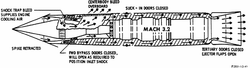
- ↑ https://ntrs.nasa.gov/citations/19650013744,"Aerodynamic Design of Axial-Flow Compressors", p. 126
- ↑ https://www.sae.org/publications/technical-papers/content/861837/, "Low Aspect Ratio Axial Flow Compressors: Why and What It Means", Wennerstrom, p. 11
- ↑ "The history of the Rolls-Royce RB211 turbofan engine | WorldCat.org". https://search.worldcat.org/title/909128142.
- ↑ https://asmedigitalcollection.asme.org/GT/proceedings/IGT1985/79429/V001T01A006/259190,"Development of a New Technology Small Fan Jet Engine", Boyd, ASME 85-IGT-139, p. 2
- ↑ https://asmedigitalcollection.asme.org/GT/proceedings/GT1969/79832/V001T01A088/231986, "An Introduction to the JT15D Engine"
- ↑ https://arc.aiaa.org/doi/abs/10.2514/1.9176?journalCode=jpp,"Ideas and Methods of Turbomachinery Aerodynamics: A Historical View", Cumpsty and Greitzer, Figure 1
- ↑ https://journals.sagepub.com/doi/10.1243/0954406991522680, "Axial Compressor Design", Gallimore, p. 439
- ↑ https://asmedigitalcollection.asme.org/turbomachinery/article-abstract/111/4/357/419178/Low-Aspect-Ratio-Axial-Flow-Compressors-Why-and?redirectedFrom=fulltext, "Low Aspect Ratio Axial Flow Compressors: Why and What It Means", Wennerstrom, SAE 861837, p. 6
- ↑ Amoo, Leye M. (2013). "On the design and structural analysis of jet engine fan blade structures". Progress in Aerospace Sciences 60: 1–11. doi:10.1016/j.paerosci.2012.08.002. Bibcode: 2013PrAeS..60....1A.
- ↑ https://asmedigitalcollection.asme.org/GT/proceedings/GT1988/79191/V002T02A017/236878,"Developing The Rolls-Royce Tay", Wilson, 88-GT-302
- ↑ The Impact Of Three-Dimensional Analysis On Fan Design, Clemmons et al., ASME 83-GT-136
- ↑ https://patents.google.com/patent/US6071077A/en, "Swept Fan Blade"
- ↑ "Modern Advances in Fan and Compressor Design using CFD", Balin, University of Colorado, Boulder, Colo. 80309
- ↑ McKinney, Randal; Cheung, Albert; Sowa, William; Sepulveda, Domingo (2007). "The Pratt & Whitney TALON X Low Emissions Combustor: Revolutionary Results with Evolutionary Technology". 45th AIAA Aerospace Sciences Meeting and Exhibit. doi:10.2514/6.2007-386. ISBN 978-1-62410-012-3. https://www.researchgate.net/publication/271367881.
- ↑ Liu, Yize; Sun, Xiaoxiao; Sethi, Vishal; Nalianda, Devaiah; Li, Yi-Guang; Wang, Lu (2017). "Review of modern low emissions combustion technologies for aero gas turbine engines". Progress in Aerospace Sciences 94: 15. doi:10.1016/j.paerosci.2017.08.001. Bibcode: 2017PrAeS..94...12L.
- ↑ "Jet Propulsion Progress", Neville and Silsbee, First Edition, McGraw-Hill Book Company, Inc., 1948, p. 127
- ↑ "Series II Goblin", Flight magazine,21st February,1946
- ↑ https://archive.org/details/in.ernet.dli.2015.19428/page/n71/mode/2up,"Gas Turbines and Jet Propulsion" 4th edition, Smith, Fig. 73 and 77
- ↑ "Westinghouse J46 Axial Turbojet Family. Development History And Technical Profiles", Paul J. Christiansen, ISBN 978-0-692-76488-6, Figure 3 and 8
- ↑ https://asmedigitalcollection.asme.org/gasturbinespower/article/132/11/116501/464800/GAS-TURBINE-COMBUSTION-Alternative-Fuels-and, p. 237
- ↑ "Two-spool Turbo Wasp", Flight magazine, 27 November 1953.
- ↑ "Gas Turbine Combustion" Third Edition, Lefebvre and Ballal, ISBN 978 1 4200 8605 8, pp. 15–16, Figure 1.16
- ↑ https://patents.google.com/patent/US20150059355A1/en,"Method And System For Controlling Gas Turbine Performance With A Variable Backflow Margin"
- ↑ http://www.netl.doe.gov>gas.turbine.handbook,"4.2.1 Cooling Design Analysis, p. 304
- ↑ "Exhaust Reheat for Turbojets - A Survey of Five Years' Development Work - Part 1", Flight magazine, 8 September 1949
- ↑ https://archive.org/details/DTIC_ADA361702,"Design Principles And Methods For Aircraft Gas Turbine Engines", RTO-MP-8, p. 19-5
- ↑ Kurzke, Joachim; Halliwell, Ian (2018). Propulsion and Power. pp. 544–545. doi:10.1007/978-3-319-75979-1. ISBN 978-3-319-75977-7. https://link.springer.com/book/10.1007/978-3-319-75979-1.
- ↑ Kurzke, Joachim; Halliwell, Ian (2018). Propulsion and Power. p. 545. doi:10.1007/978-3-319-75979-1. ISBN 978-3-319-75977-7. https://link.springer.com/book/10.1007/978-3-319-75979-1.
- ↑ "Fast Jets-the history of reheat development at Derby", Cyril Elliott, Rolls-Royce Heritage Trust, Technical Series No 5, ISBN 1 872922 20 1, p. 116
- ↑ "A Review Of Supersonic Air Intake Problems, Wyatt", Agardograph No. 27, p. 22
- ↑ The First James Clayton Lecture,"The Early History Of The Whittle Jet Propulsion Gas Turbine", Air Commodore F. Whittle, p. 430 Fig. 20
- ↑ Not Much Of An Engineer, Sir Stanley Hooker An Autobiography, ISBN 1 85310 285 7, p. 90
- ↑ https://patents.google.com/patent/US3477455A/en,"Supersonic inlet for jet engines"
- ↑ https://ntrs.nasa.gov/citations/19930090035,"Use of Shock-trap Bleed to Improve Pressure Recovery...",
- ↑ https://www.semanticscholar.org/paper/Ramjet-Intakes-Cain/96dc23a101c094f19d185f7497755c0cb0d19ec8, "Ramjet Intakes", Cain, Figure 19
- ↑ "Fluid-dynamic Drag", Hoerner 1965, Library of Congress Catalog Card Number 64-19666, Chapter 5 Drag of surface imperfections, p. 5-1
- ↑ https://www.hindawi.com/journals/ijae/2022/3637181/, Analysis of Entropy Generation and Potential Inhibition in an Aeroengine System Environment, Liu et al., Introduction
- ↑ https://www.cambridge.org/core/journals/aeronautical-journal/article/abs/aircraft-propulsion-from-the-back-room/771675086CDE0E766BE700CD6B3198E7 "Aircraft propulsion from the back room", Hawthorne, p. 101
- ↑ "Seal Technology In Gas Turbine Engines", AGARD CP 237, pp. 1–2
- ↑ Selecting a Material For Brazing Honeycomb in Turbine Engines, Sporer and Fortuna, Brazing and Soldering Today February 20014, p. 44
- ↑ https://patents.google.com/patent/US2963307, "Honeycomb seal" Fig.1
- ↑ https://www.yumpu.com/en/document/view/33920940/8th-israeli-symposium-on-jet-engine-and-gas-turbine, slide 'Effect of tip clearance on turbine efficiency'
- ↑ Current Aerodynamic Issues For Aircraft Engines, Cumpsty, 11th Australian Fluid Mechanics Conference, University of Tasmania, 14–18 December 1992, p. 804
- ↑ CFM Flight Ops Support, Performance Deterioration p. 48
- ↑ AGARD CP 237 'Gas Path Sealing in Turbine Engines', Ludwig, Figure 6(a)
- ↑ https://ntrs.nasa.gov/citations/19780013166 "Gaspath Sealing in Turbine Engines", Ludwig Fig. 6(d)
- ↑ 117.0 117.1 AGARD CP 237 'Gas Path Sealing in Turbine Engines', Figure 6(a)
- ↑ AGARD CP 237 'Gas Path Sealing in Turbine Engines', Figure 7(b)
- ↑ "Jet Engines And Propulsion Systems For Engineers, GE Aircraft Engines 1989, pp. 8–10
- ↑ https://ntrs.nasa.gov/citations/20060051674 "Transient tip clearance" fig.1
- ↑ https://patents.google.com/patent/US6126390A/en "Passive clearance control system for a gas turbine"
- ↑ "Turbine Engine Clearance Control Systems: Current Practices and Future Directions". September 2002. https://ntrs.nasa.gov/citations/20030003697.
- ↑ https://www.easa.europa.eu/en/document-library/product-certification-consultations/proposed-special-condition-1, EASA "Turbine Engines Transient over-temperature, over-speed and over-torque limit approval", 'When the engine characteristics are such that an acceleration from cold produces a transient over-temperature in excess of that for steady state running...'
- ↑ Training Manual CFM56-5A Engine Systems, Clearance Control Chapters 75-21-00 and 75-22-00
- ↑ https://arc.aiaa.org/doi/book/10.2514/4.867293 "The Engines of Pratt & Whitney:A Technical History", Connors, p. 219
- ↑ https://www.enginehistory.org,"Wright's T35 Turboprop Engine, et al. by Doug Cuty, 1 Sept 2020 "... a constant outer diameter and a pressure ratio of 8:1 ... seal leakage was so bad that the constant outer diameter approach was terminated."
- ↑ 'Honeycomb Seal", US patent 2,963,307
- ↑ https://archive.org/stream/DTIC_ADA060293/DTIC_ADA060293_djvu.txt, "AGARD CP 237", pp. 1–9
- ↑ "Jet Engine Force Frame", US patent 3,675,418
- ↑ https://nyaspubs.onlinelibrary.wiley.com/doi/abs/10.1111/j.1749-6632.1968.tb15216.x, "Development Of The High Bypass Turbofan", p. 588 'Advanced Structural Concepts'
- ↑ "747 Creating The World's First Jumbo Jet And Other Adventures From A Life In Aviation", Sutter, ISBN 978 0 06 088241 9, p. 187
- ↑ Flight International,13 November 1969, p. 749
- ↑ Koff, B. (1991). "Spanning the globe with jet propulsion". 21st Annual Meeting and Exhibit. American Institute of Aeronautics and Astronautics. p. 8. doi:10.2514/6.1991-2987. https://arc.aiaa.org/doi/10.2514/6.1991-2987.
- ↑ https://patents.google.com/patent/US5320307A/en, "Aircraft Engine Thrust Mount", Abstract
- ↑ 135.0 135.1 https://www.freepatentsonline.com/5873547.html, "Aircraft Engine Thrust Mount", Sheet 2
- ↑ https://archive.org/details/boeing-777-ian-allan-abc, "Boeing 777, Campion-Smith, p. 52
- ↑ https://asmedigitalcollection.asme.org/memagazineselect/article-abstract/133/03/46/380174/Mounting-TroublesThe-First-Jumbo-Jet-was-an?redirectedFrom=fulltext, "Mounting Troubles", Langston, p. 7
- ↑ https://ntrs.nasa.gov/citations/19820020420, NASA CR-165573, Figure 4-1 'Inlet angle of attack'
- ↑ https://ntrs.nasa.gov/citations/19790012903,"CF6 jet engine performance improvement program. Task 1: Feasibility analysis", Fig.31
- ↑ Load distributing Thrust Mount, US patent 3,844,115, column 1 line 66
- ↑ Langston, Lee S. (2011). "Mounting Troubles". Mechanical Engineering 133 (3): 46–49. doi:10.1115/1.2011-MAR-6.
- ↑ https://ntrs.nasa.gov/citations/19790022018, "Energy Efficient Engine Flight Propulsion System",'Mounting System' 4.11.2.3
- ↑ "Flight", February 6, 1947, "The de Havilland Ghost (DGT/50)", p. 143
- ↑ "Gas path sealing in turbine engines", Ludwig, NASA TM-73890, p. 1-2, 2. Sealing locations and seal types
- ↑ Training Manual CFM56-5C Engine Systems, January 2003, Published by CFMI Customer Training Center, Chapter 79-00-00 page 7
- ↑ Aircraft Engine Diagnostics, NASA CP 2190, 1981, JT8D Engine Performance Retention, p. 64
- ↑ https://smart cockpit.com, CFM Flight Operations Support, page 37
- ↑ https://reposit.haw-hamburg.de/handle/20.500.12738/5576,"Further investigation of engine performance loss, in particular exhaust gas temperature margin, in the CF6-80C2 jet engine and recommendations for test cell modifications to record additional criteria, Tables 2.1–2.4
- ↑ https://ntrs.nasa.gov/citations/19810022654,"Aircraft Engine Diagnostics", JT-8D Engine Performance Retention, p. 66
- ↑ Flight International, 13 November 1969, p. 749
- ↑ CFM CFM56 Series Training Manual, p. 142
- ↑ Plante, Robert D. (1988). "The Nozzle Guide Vane Problem". Operations Research 36 (1): 18–33. doi:10.1287/opre.36.1.18.
- ↑ Jet Engines And Propulsion Systems For Engineers, GE Aircraft Engines 1989, pp. 5–17
- ↑ https://asmedigitalcollection.asme.org/GT/proceedings/GT1962/79931/V001T01A016/227591,"American Airlines Experience with Turbojet/Turbofan Engines", p. 4
- ↑ https://ntrs.nasa.gov/citations/19750018937, p. 2
- ↑ https://ntrs.nasa.gov/citations/19750018937,"Analysis of turbofan engine performance deterioration and proposed follow-on tests", p. 22
- ↑ https://ntrs.nasa.gov/citations/19750018937 p.20
- ↑ https://ntrs.nasa.gov/citations/19750018937, Fig.13
- ↑ https://ntrs.nasa.gov/citations/19810022654,"Aircraft Engine Diagnostics", JT-8D Engine Performance Retention, p. 69
- ↑ https://archive.org/details/gasturbinecombus0000lefe, Gas Turbine Combustion, Lefebvre 1983, ISBN 0 07 037029X p. 4
- ↑ CFM Flight Ops Support 13 December 2005, p. 85
- ↑ "Performance Prediction and Simulation of Gas Turbine Engine Operation for Aircraft, Marine, Vehicular, and Power Generation", RTO Technical Report TR-AVT-036, pp. 2–50
- ↑ "Aircraft Propulsion", P. J. McMahon, ISBN 0 273 42324 X, p. 58
- ↑ Hirschel, Ernst Heinrich; Prem, Horst; Madelung, Gero (2004). Aeronautical Research in Germany. p. 226. doi:10.1007/978-3-642-18484-0. ISBN 978-3-642-62129-1. https://link.springer.com/book/10.1007/978-3-642-18484-0.
- ↑ "Evolution Of The Airliner", Whitford, ISBN 978 1 86126 870 9, p. 119
- ↑ Engineering Thermodynamics Work and Heat Transfer, Rogers and Mayhew 1967, ISBN 978-0-582-44727-1, p. 15
- ↑ https://archive.org/details/masslengthtime0000norm_v5r2/page/150/mode/2up, Mass, Length and Time, Norman Feather 1959, p. 150

 |  |

![Klimov VK-1F turbojet with afterburner. An afterburner is a propulsive duct in which high velocity exhaust from an engine turbine is converted into pressure in a diffuser. Afterburner fuel is burned with the oxygen in the dilution air which was not involved in the engine combustion process. The gas expands in a nozzle with an increase in velocity. The turbojet afterburner has the same three requirements as a ramjet, both being propulsive ducts. These are conversion of high velocity gas into pressure in a diffuser, combustion and expansion to a higher velocity in a nozzle. The turbojet/afterburner combination was sometimes considered in the late 1940s a turbo-ramjet.[34][35]](/wiki/index.php?title=Special:Upload&wpDestFile=Klimov_VK-1F_(1948)_used_in_MiG_17_at_Flugausstellung_Hermeskeil,_pic2.jpg)
.jpg)
![1970 Garrett TFE731 with an early example of a transonic (supersonic relative velocities over the outer part of the blade) fan designed with the help of three-dimensional computational fluid dynamics (CFD).[81]](/wiki/index.php?title=Special:Upload&wpDestFile=JET_ENGINES_-_NARA_-_17421181.jpg)
![General Electric J31 with ten reverse-flow combustors. Compressed air flows between the 18-8 stainless steel outer casing and inner Inconel flame tube, then through a series of holes to the inside of the tube where it mixes with fuel. Burning continues along the length and is complete before reversing direction to the turbine.[86]](/wiki/index.php?title=Special:Upload&wpDestFile=General_Electric_J31NMUSAF_(070110-F-1234S-009).jpg)
![Rolls-Royce Nene with nine combustion chambers. The cutaway is one of 2 chambers fitted with a flame igniter which places the igniter in a cooler location than directly in the hot gas stream. During a start atomized fuel from the small self-contained unit (orange-coloured solenoid shown) is ignited by its ignition plug and the flaming jet of fuel is projected into the main fuel spray from the burner. Combustion is propagated to all the chambers through interconnecting tubes.[88]](/wiki/index.php?title=Special:Upload&wpDestFile=Combustor_on_Rolls-Royce_Nene_turbojet_(2).jpg)
![Rolls-Royce Turbomeca Adour military turbofan. There is a requirement to maintain a certain minimum pressure-loss in combustors, rather than reducing it as much as possible to minimize entropy production. It has to be maintained to prevent backflow in the turbine cooling circuits since cooling air from the HP compressor needs a lower pressure at the turbines in order to flow.[93][94] Cooling air from the compressor (blue) has to flow to the turbine area (nozzle guide vane painted orange). This is enabled by the drop in pressure which occurs in the combustor. Also evident is the increase in area from the compressor into the combustor which is necessary to slow the air.](/wiki/index.php?title=Special:Upload&wpDestFile=Core_section_of_a_sectioned_Rolls-Royce_Turbom%C3%A9ca_Adour_turbofan.jpg)
.jpg)