Engineering:Compressor characteristic
Compressor characteristic is a mathematical curve that shows the behaviour of a fluid going through a dynamic compressor. It shows changes in fluid pressure, temperature, entropy, flow rate etc.) with the compressor operating at different speeds. A compressor increases the pressure of a fluid passing through it, so that the exit pressure is higher than the inlet pressure. Due to this property, compressors are used in a wide range of machines, such as refrigerators, cars, jet engines and industrial processes.
Compressor characteristic curves are plotted between various parameters and some are as follows[1]
Pressure ratio vs. non-dimensional flow rate
Performance of a compressor is usually specified by curves of delivery pressure against mass flow rate for various fixed values of rotational speed and inlet temperature.[2][3][4] These performance characteristic curves are usually plotted with dimensionless variables. For this, we start with implicit functional relationships for all the variables as [4]
Where
- = characteristic linear dimension of the compressor
- = rotational speed
- = mass flow rate
- and = stagnation pressure at compressor inlet and outlet
- and = stagnation temperature at compressor inlet and outlet
- = characteristics gas constant
By making use of π-theorem, we obtain the non-dimensional groups (π terms) as [4]
- , , ,
When we are concerned with the performance of a machine of fixed size compressing a specified gas and D may be omitted from the groups and we can write
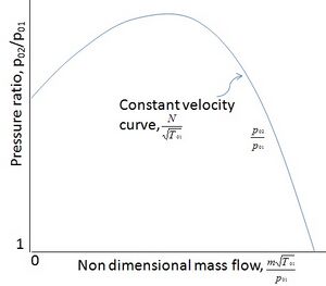
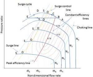
Though the terms and are truly not dimensionless, they are referred as 'non-dimensional mass flow' and 'non-dimensional rotational speed' for practical purpose. The stagnation pressure ratio is plotted against in the form of family of curves, each curve of a family being drawn for fixed values of as shown in Figure 1.
Pressure rise vs. flow rate
The plot between pressure rise and flow rate is same as pressure ratio vs. mass flow rate with a small difference as in here we take pressure difference between inlet and outlet of the compressor instead of their ratio.[4]
Loading coefficient/pressure coefficient vs. flow coefficient
First we have to know about the loading, pressure and flow coefficient which are as follow-[4]
- Loading coefficient
So we can see that
Where
- = impeller tip speed
- = head
and also
So assuming a function to relate Loading coefficient and the Flow coefficient
A compressor gives its best performance while operating at its design point but it is also expected to operate away from the design point. Therefore, knowledge about its behavior at off-design operation is also necessary. The quantity can be assumed constant in a wide range of incidence. This is justified in view of small variations in the air angles at the rotor and stator exits. Therefore, writing
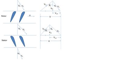
Where
- = blade peripheral velocity
- and are absolute air velocity at the rotor inlet and outlet
- and are relative velocity at rotor inlet and outlet
- = absolute air velocity at the stator outlet
- and are the angles shown in the following Figure 2.
If the design values are identified by the superscript
At off-design conditions [4]
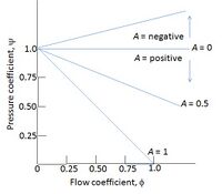
This equation also gives the off-design characteristic of an axial-flow compressor. The figure shown below depicts theoretical characteristic curves for some values of the constant . For positive values of , the curves are falling, while for negative values rising characteristics are obtained.
Theoretical characteristic curve
Theoretical characteristic curve of the compressor is the plot to show behavior of the fluid without considering losses due to shock and friction[7][8] as it passes through the compressor at different constant speeds. The curve as shown in Figure 3. is plotted between pressure coefficient and flow coefficient for different values of as shown in fig. From fig. It is clear that as the flow coefficient increases the pressure gained per unit mass flow rate of the fluid decreases and due to this pressure coefficient at higher mass flow rate will be low.
Actual characteristic curve
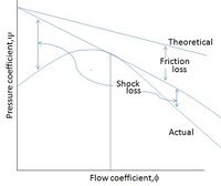
Actual characteristic curve of the compressor is the modified version of the theoretical characteristic curve. In this we take care of both shock and friction losses as shown in the Figure 4. As seen in the figure the steepness of the curve increases at higher mass flow rates because since there will be higher frictional losses at high flow coefficient (Darcy's friction law).[9][10]
Surging
Surging is the complete breakdown of steady flow in the compressor which occurs at low flow rate. Surging takes place when compressor is operated off the design point and it affects the whole machine and this is aerodynamically and mechanically undesirable. It can damage the rotor bearings, rotor seals, compressor driver and affect the whole cycle operation. It results in high temperature, high vibration and leads to flow reversal.[4][11][12]
Surge process
Assuming the compressor operates at point A () on the characteristic curve (let at constant speed ) as shown in Figure 5. Now if the flow rate is reduced to by closing a control valve on the delivery pipe, the static pressure upstream of the valve is increased. This increased pressure () is then matched by the increased delivery pressure (at B) which is developed by the compressor. Now further reducing the flow (to and ), the increased pressures in the delivery pipe are again matched by the compressor delivery pressures at C and S on the characteristic curve.
On the characteristic curve at the flow rates below ṁS provides lower pressure as seen in the fig. at D and E. But now the pipe pressures due to further reduction of flow by valve (let at point D) will be higher than the pressure at D and E. This unbalance between the pipe pressure and the compressor delivery pressure only exist for a very short time. This is because there is higher pressure in the pipe than the gas pressure produced by the compressor and due to this reversing of the flow takes place and it leads to a complete break-down of the normal steady flow from the compressor to the pipe.
Surge cycle
Due to flow reversal, pressure in the pipe falls and the compressor regains its normal stable operation (let at point B) delivering the gas at higher flow rate (). But the control valve still corresponds to the flow rate . Due to this compressor's operating conditions will again return to D through points C and S. And due to lower compressor pressure, the pressure falls further to and the entire phenomenon from point E to D repeats again and again and this cycle EBCSDE known as the surge cycle.
Surge point
Surge points are the peak points on the characteristic curves (as in Figure 5.) left of which the pressure generated by the compressor is less than the pipe pressure and these points initiates the surge cycle. These points on the curves are shown in the fig. by point S.[4]
Surge line
Surge line is the line which connects the surge points (S) on each characteristic curve corresponding to different constant speeds. The stable range of operation for the compressor is on the right hand side of the surge line.
Surge control line
Surge control line is the line which works as the indicating line for the surge control mechanism so that surge can be prevented in the system and proper steps can be taken. The line can vary for different surge control systems as it is up to the system to decide the margin between operating point and the surge point. [13]
Surge margin
Surge margin is the indicator to show that how close is the system to the surge. It is different for the different surge control system as they employ different surge control lines.[14] The basic surge margin can be defined as
- Surge margin =
Where
- = mass flow rate at surge control line at a particular constant speed
- = mass flow rate at surge line at the same constant speed.
Stalling
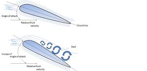
Stalling is the separation of flow from the compressor blade surface as shown in the Figure 6. At low flow rates the angle of attack increases over the critical or maximum angle that the aerodynamic profile can sustain, and due to this there occurs the flow separation on the suction side of the blades which is known as positive stalling. If the flow separation occurs on the pressure side of the blade then it's known as negative stalling and this occurs due to negative attack angle. But generally positive stalling is taken into consideration.
In the compressor at high pressure stages if there occurs a deviation from design point (at which compressor is designed to operate) the angle of attack exceeds its stalling value and stall cells (which are the regions where fluid starts to whirl at a particular location and doesn't move forward) to form at hub and tip of the blade. The size of these cells increases with decreasing flow rate. If the flow rate is further reduced these cells grow larger and it affects the whole blade height and this causes significant drop in the delivery pressure and at very low flow rate, flow reversal takes place which is known as surge. It also results in drop in stage efficiency of the compressor and its delivery pressure.[15]
Other compressor phenomena
Following are some other characteristics of the compressor
Choke/Stonewall point
Choking is the condition which occurs in the compressor in which it operates at very high mass flow rate and flow through the compressor can't be further increased as mach number at some part of the compressor reach to unity i.e. to sonic velocity and the flow is said to be choked. In compressor maximum volume flow rate is limited by cross-section at the inlet. This condition can be seen in the right side of the Figure 5. in which constant speed lines descends steeply. The point on constant speed line at which choking occurs is known as choke point or stonewall point. [16]
Choke line
Choke line is the line joining the choke points on different constant speed lines in the Figure 5. In simple words, the operation on right side of choke line is very inefficient, but is possible if the exit static pressure is low enough and blade instabilities such as choke flutter are avoided.
Constant efficiency lines
Constant efficiency lines are the elliptical shaped curves in the compressor characteristic curve along which the efficiency of the compressor remains constant.
Maximum allowable speed
This is the maximum speed at which compressor can work properly(shown as in Figure 5.) and beyond this speed limit stresses and vibrations in the compressor crosses the prescribed limit and this can damage the compressor and to control this, compressor's speed is lowered.
Minimum required speed
This is the minimum speed at which compressor should operate (shown as in Figure 5.) and below this limit compressor can't increase the pressure of inlet fluid and goes into idle condition.
References
- ↑ Gravdahl, Jan Tommy; Egeland, Olav (2012-12-06) (in en). Compressor Surge and Rotating Stall: Modeling and Control. Springer Science & Business Media. ISBN 978-1-4471-0827-6. https://books.google.com/books?id=ODT2BwAAQBAJ&q=Compressor+characteristic&pg=PA24.
- ↑ Klassen, H.A., `Performance of low pressure ratio centrifugal compressors with four diffuser designs`, NACA, TN 7237, March 1973.
- ↑ Nahimo, T. Et al., `Effect of Reynolds number on performance characteristics of centrifugal compressors with special reference to configurations of impellers`, ASME paper No.74-GT-59, 1974.
- ↑ 4.00 4.01 4.02 4.03 4.04 4.05 4.06 4.07 4.08 4.09 Yahya ,S.M, ”Turbine, Compressors & Fans”,4TH ED.McGraw Hill,2011.
- ↑ Horlock, J.H., Axial Flow Turbines, Kruger Publishing Co., 1973.
- ↑ Horlock, J.H., Axial Flow Compressors, Kruger Publishing Co., 1973.
- ↑ Ferguson, T.B., The Centrifugal Compressor Stage, Butterworth, London, 1963.
- ↑ Whitfield, A. and Wallace, F.J., `Study of incidence loss models in radial and mixed flow turbomachinery`, Instn. Mech. Engrs. Conference Publication, 3, paper No. C55/73, 1973.
- ↑ Watanabi, I. and Sakai, T., `Effect of the cone angle of the impeller hub of the mixed flow compressor upon performance characteristics`, SAE paper No. 996A, 1965.
- ↑ Whitfield, A. and Wallace, F.J., `Performance prediction for automotive turbocharger compressors`, Proc. Instn. Mech. Engrs. 1975.
- ↑ Greitzer, E.M., `Surge and rotating stall in axial flow compressors`, ASME J. Eng. Power, Vol. 98. No. 2, April 1967.
- ↑ Tsui, Chih-Ya et al., ` An experiment to improve the surge margin by use of cascade with splitter blades`, J. Eng. Thermophys,, Vol. 1, no. 2, May 1980.
- ↑ "Archived copy". http://www.gmrc.org/documents/GMRCSurgeGuideline_000.pdf.
- ↑ Cumpsty, N. A. (1989). Compressor Aerodynamics. Longman.
- ↑ Howell, A. R. (1942). The present basis of axial flow compressor design: Part 1, Cascade theory and performance. ARC R and M. 2095.
- ↑ "Design and Function of a Turbocharger - Compressor | BorgWarner Turbo Systems". http://www.turbos.bwauto.com/en/products/turbochargerCompressor.aspx.
