Engineering:Electric turbo compound

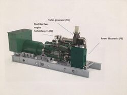
An Electric Turbo Compound (ETC) system is defined where a turbine coupled to a generator (turbogenerator) is located in the exhaust gas flow of a reciprocating engine to harvest waste heat energy and convert it into electrical power. An example of an ETC system is where a turbogenerator is located downstream of a turbocharger turbine of an Internal Combustion Engine (ICE). The power generated from the ETC system can be used to feed into an electrical grid or provide power to local electrical loads such as engine auxiliaries.[1]
ETC systems are commercially available for stationary power gensets and at an advanced stage of development for automotive applications as a solution to the challenge of improving the fuel efficiency of gas and diesel engines by recovering waste energy from the exhaust gases.[2]
System architecture and working principle of ETC

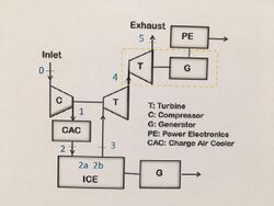
Description of an ETC system on a turbocharged ICE
The ETC system is typically located downstream of the turbocharger of an ICE. The exhaust gases expand first through the turbocharger turbine and then through the ETC turbine, which drives a high-speed alternator generating DC or AC power. In gensets, this extra power is added to the power output from the primary generator, increasing the system efficiency. For automotive application the ETC would become the primary generator used to power the vehicle’s auxiliary systems.[3] It is claimed that an Electric Turbo Compounded ICE can achieve SFC (Specific fuel consumption) improvements in the range of 4-6%.[4]
Impact of ETC on a turbocharged ICE
In order to recover the exhaust gas energy after the turbocharger turbine (TC), it is necessary to create an additional expansion step which increases the engine backpressure; this results in the following effect:
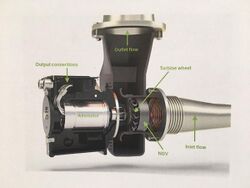
- Change of turbocharger turbine operating point: the engine backpressure increase makes it necessary to rematch the turbocharger turbine by changing the turbine wheel or the Nozzle Guide Vane (NGV) angle.
- Reduction in engine power output: the Pistons have to provide more work to push the exhaust out of the cylinder, slightly decreasing the engine crankshaft work output.
- Reduction in volumetric efficiency: marginally more of the exhaust gases are trapped in the cylinder during scavenging, leaving less space for the fresh air to come in.
Nevertheless, the power produced by the ETC system more than compensates for this power loss in the engine and therefore provides an overall efficiency improvement for the system.
Turbo generator

The Turbo Generator (TG) comprises a turbine and an alternator. The turbine typically consists of a turbine wheel, nozzle guide vanes (NGV) and the volute. The turbine wheel can be axial or radial and can be directly coupled to a high-speed alternator which results in a compact and efficient machine.
Although standard turbogenerator technology is not new [TG patent, 1923], the development of high-speed turbogenerator technology is relatively modern with significant development occurring during the 1990s. Challenges associated with high-speed turbogenerators are:
- stresses and heat generated in the rotor of the electrical machine due to the high rotational speeds
- Rotordynamics of the turbogenerator system
- mass production of cheap, yet reliable, robust and highly efficient turbine equipment for hot exhaust gases
Power conversion electronics

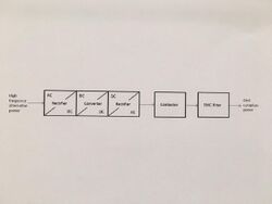
The Power electronics control the turbo generator operation and convert high frequency unregulated alternating current into either AC 50/60 Hz or DC power for vehicle applications.
The power electronics architecture can have different configurations but may consist of a rectifier, a converter, and an inverter stage. The rectifier transforms the unregulated AC into a DC power. As the turbo generator output voltage depends on speed and load, the rectified voltage is subsequently regulated to a fixed voltage by a converter stage. For AC applications the inverter transforms DC to AC and synchronizes it with the electricity grid. A contactor connects or disconnects the inverter output to the grid depending on whether the grid is within specification. The EMC (electromagnetic compatibility) filter reduces the high-frequency emissions from the power electronics and improves its immunity to high-frequency interference and transients from the grid.
A brief evolution of Electric Turbo Compounding (ETC) systems
Turbo-compound engines have been used for piston aircraft engines since the late 1950s until superseded by turboprop and turbojet engines. In the 1980s the mechanical turbo compound was applied in motorsport racing cars and in the 1990s in heavy truck diesel engines. In 2001, Caterpillar launched a program to develop an Electric Assisted Turbocharger (EAT) for truck applications.[5]
In 2004, the first ETC prototype was created for the heavy truck industry by Bowman Power Ltd in partnership with John Deere. In 2009, Bowman Power Ltd developed an ETC system for the power generation industry. In 2010, Controlled Power Technologies (CPT) designed an ETC system called TIGERS for passenger car applications (Green cars congress reference2010). In 2014, F1 includes heat recovery technology to complement kinetic energy recovery under the name MGU-H to boost the engines power output.
Advantages of using ETC
- Improves overall efficiency of the genset, including fuel input costs and helping end-users reduce amount of fuel burned.[6]
- Typically 4-7% less fuel consumption and carbon emissions for both diesel and gas gensets.[7]
- Increased power density and output capacity with improved fuel efficiency.[8]
- The cost of generating power through waste heat recovery is substantially less than burning more fuel, even with low diesel prices.[9]
- Helps developing economies with unreliable or insufficient power infrastructure.[10]
- Gives independent power providers (IPPs), power rental companies and generator OEMs (original equipment manufacturers) a competitive advantage and potential increased market share.
Disadvantages of using ETC
- Upfront costs incur an additional expense for businesses.
- The need to update existing turbomachinery and recertification of the unit adds additional costs and can be time consuming.[11]
- There will be additional weight to add an ETC to a current unit.
- challenges with high-speed turbo generators such as high stress in the rotors, heat generation of the electrical machine and rotordynamics of the turbogenerator system.
Exhaust Energy Recovery Systems
Exhaust energy recovery systems may play an increasingly important role to meet the exhaust emission regulations and to improve fuel efficiency for today’s on-highway, off-highway and power generation markets globally. Exhaust recovery systems work by either converting the exhaust energy into mechanical or electrical energy or to transfer the energy for heating purposes.
Importance of energy recovery in an ICE
The operating cost of an ICE can be very significant, for example, a continuously operated 1 MWe diesel generator set may have an annual fuel bill which could represent more than five times the capital cost of the generator set. The exhaust gas of an ICE contains 30% to 40% of the chemical fuel energy as heat.[12][13] As a consequence, even a limited recovery of this energy would represent a significant contribution in terms of overall system efficiency improvement.
References
- ↑ J., Talbot-Weiss (2009). "SFC improvements from turbo-generating heavy-duty diesel engines". University of Sussex.
- ↑ Evaluation of CO2 reduction in SI engines with Electric Turbo-Compound by dynamic powertrain modelling. doi:10.1016/j.ifacol.2015.10.014.
- ↑ "Diesel Engine Waste Heat Recovery Utilizing Electric Turbocompound Technology". http://www.osti.gov/scitech/servlets/purl/827993.
- ↑ "Turbo Compounding Technology". 2014. http://www.bowmanpower.com/products/what-is-etc/.
- ↑ "La voiture doppee par les gaz d'echapement". Science & Vie. 20 February 2008. http://www.heat2power.net/press/heat2power_dans_Science_et_Vie_-_Mars_2009.pdf.
- ↑ "Electric Turbo-Compounding: Helping make distributed power systems more efficient". Kenya Engineer. https://www.kenyaengineer.co.ke/electric-turbo-compounding-helping-make-distributed-power-systems-more-efficient/. Retrieved 2018-02-08.
- ↑ "Less Fuel, Reduced CO2". Bowman Power. https://www.bowmanpower.com/benefits/less-fuel/. Retrieved 2018-02-08.
- ↑ "Turbo Compounding, A Technology Who's Time Has Come". Carl T. Vuk - John Deere. https://energy.gov/sites/prod/files/2014/03/f9/2005_deer_vuk.pdf. Retrieved 2018-02-08.
- ↑ "Competitive Advantage". Bowman Power. https://www.bowmanpower.com/benefits/competitive-advantage. Retrieved 2018-02-08.
- ↑ "Modelling a Turbogenerator for Waste Heat Recover on a Diesel-Electric Hybrid Bus". Ian Briggs. http://www4.dcu.ie/sites/default/files/conference_sbc/Ian%20Briggs_Queens.pdf. Retrieved 2018-02-08.
- ↑ "Modelling a Turbogenerator for Waste Heat Recover on a Diesel-Electric Hybrid Bus". Ian Briggs. http://www4.dcu.ie/sites/default/files/conference_sbc/Ian%20Briggs_Queens.pdf. Retrieved 2018-02-08.
- ↑ Vuk, C. (2006). Electric Turbo Compounding, A Technology Who's Time Has Come.
- ↑ Cipollone, R. (2013). "Gualtieri, Turbo compound systems to recover energy in ICE". International Journal of Engineering and Innovative Technology (IJEIT).
Further reading
- 'La voiture doppee par les gaz d'echapement', 2009. [Online] [Accessed: 15- Dec- 2014].
- Aeristech, 'Advanced Boosting: Electric Superchargers / Compressors and Full Electric Turbochargers', 2014. [Online] [Accessed: 18- Dec- 2014].
- S. Groove, M. Harrison, D. Gudd and J. Bell, 'Investing F1's new dawn', ENGINE TECHNOLOGY TURBOCOMPOUNDING, 2011.
- A. Greszler, 'Diesel Turbocompound', 2008. [Online] [Accessed: 12- Dec- 2014].
- Deere & Company, Moline, IL (US), 'ELECTRIC TURBO COMPOUND CONFIGURATION FOR AN ENGINE/ELECTRIC GENERATOR SYSTEM', US 7,047,743 B1, 2006.
- A. Romagnoli, A. Bin-Mamat and R. Martinez-Botas, 'Design and development of a Low-Pressure Turbine (LPT) for turbocompounding applications using RICARDO WAVE', https://www.ricardo.com, 2013. [Online] [Accessed: 12- Dec- 2014].
- N. Watson and M. Janota, Turbocharger: the Internal Combustion Engine. London: THE MACMILLAN PRESS LTD, 1982.
- Aeristech, 'Turbine Generators', 2014. [Online] [Accessed: 18- Dec- 2014].
- Diesel Engine Waste Heat Recovery Utilizing Electric Turbocompound Technology. 1st ed. Accessed January 5, 2015.
- A. Legros, L. Guillaume, M. Diny and V. Lemort, 'Comparison and Impact of Waste Heat Recovery Technologies on Passenger Car Fuel Consumption in a Normalized Driving Cycle', Energies, vol. 7, no. 1996-1073, pp. 5273-5290, 2014.
- S. Rajoo, A. Romagnoli, R. MartinezBotas, A. Pesiridis, C. Copeland and A. Bin Mamat, AUTOMOTIVE EXHAUST POWER AND WASTE HEAT RECOVERY TECHNOLOGIES, 1st ed. 2015.
- heat2power, 'Heat to power conversion benchmark'. [Online] [Accessed: 05- Jan- 2015].
