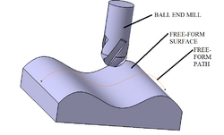
Engineering:Freeform surface machining

In manufacturing, freeform surface machining refers to the machining of complex surfaces that are not uniformly planar. The industries which most often manufactures free-form surfaces are basically aerospace, automotive, die mold industries, biomedical and power sector for turbine blades manufacturing. Generally 3- or 5-axis CNC milling machines are used for this purpose. The manufacturing process of freeform surfaces is not an easy job, as the tool path generation in present CAM technology is generally based on geometric computation so tool path are not optimum. The geometry can also be not described explicitly so errors and discontinuities occurrence in the solid structure cannot be avoided. Free-form surfaces are machined with the help of different tool path generation method like adaptive iso-planar tool path generation, constant scallop tool path generation, adaptive iso-parametric method, iso-curvature, isophote and by other methods. The different methods are chosen based on the parameters which is needed to be optimized.[1][2]
Different tool path generation methods
- Iso-planar tool path method: This is the most common and robust method used to machine free-form surface. In this process tool path generation is done by intersection of surfaces with parallel plane in Cartesian space.
- Adaptive iso-planar tool path method: In this process the surface are partitioned into different regions according to their slope with the intersection planes by applying the concept of isophote.
- Iso-scallop method: Scallop generated between two adjacent machining path is constant.[3][4]
Optimization of free-form surface machining
CAM software generally creates a tool path without considering any mechanics process. These causes risk of tool damage, tool deflection and errors on surface finish. By minimizing the forces we can increase tool life. Different optimization method can be used considering process parameters like feed rate, spindle speed, steps, tool diameter, magnitude and preset maximum force. The optimization can be done for minimum machining time, minimum tool travel, minimum production cost or for good surface finish. Efficiency of surface machined is also considered by maximum scallop height and by gouging. Gouging are the main reason for discrepancies of surface accuracy and texture specification. It also causes damage to part,s surface and machine tool. Scallop height tolerance help us in measuring the quality of free-form surface. Selection of proper topology result in minimum path length. In CAM software choosing NURBS to create surface is considered to be good method for presenting surface as it is accepted by both IGES and STEP files of CAM software.[5]
See also
References
- ↑ Lazoglu, I (2009). "Tool path optimization for free form surface machining". CIRP Annals - Manufacturing Technology 58 (2009): 101–104. doi:10.1016/j.cirp.2009.03.054.
- ↑ Ding, S (February 2003). "Adaptive iso-planar tool path generation for machining of free-form surfaces". Computer-Aided Design 35 (2): 141–153. doi:10.1016/s0010-4485(02)00048-9.
- ↑ Kumar, Rajneesh (2006). "Optimization of CNC iso-scallop free form surface machining using a genetic algorithm". International Journal of Machine Tools and Manufacture 46 (7–8): 811–819. doi:10.1016/j.ijmachtools.2005.07.028.
- ↑ Lasemi, Ali (2010). "Recent development in CNC machining of freeform surfaces: A state-of-the-art review". Computer-Aided Design 42 (7): 641–654. doi:10.1016/j.cad.2010.04.002.
- ↑ Poniatowska, Malgorzata (2015). "Free-form surface machining error compensation applying 3D CAD machining pattern model". Computer-Aided Design 62: 227–235. doi:10.1016/j.cad.2014.12.003.
 |
