Engineering:Minimum-shift keying
| Passband modulation |
|---|
| Analog modulation |
| Digital modulation |
| Hierarchical modulation |
| Spread spectrum |
| See also |
In digital modulation, minimum-shift keying (MSK) is a type of continuous-phase frequency-shift keying that was developed in the late 1950s by Collins Radio employees Melvin L. Doelz and Earl T. Heald.[1] Similar to OQPSK, MSK is encoded with bits alternating between quadrature components, with the Q component delayed by half the symbol period.
However, instead of square pulses as OQPSK uses, MSK encodes each bit as a half sinusoid.[2][3] This results in a constant-modulus signal (constant envelope signal), which reduces problems caused by non-linear distortion. In addition to being viewed as related to OQPSK, MSK can also be viewed as a continuous-phase frequency-shift keyed (CPFSK) signal with a frequency separation of one-half the bit rate.
In MSK the difference between the higher and lower frequency is identical to half the bit rate. Consequently, the waveforms used to represent a 0 and a 1 bit differ by exactly half a carrier period. Thus, the maximum frequency deviation is δ = 0.5 fm where fm is the maximum modulating frequency. As a result, the modulation index m is 0.5. This is the smallest FSK modulation index that can be chosen such that the waveforms for 0 and 1 are orthogonal. A variant of MSK called Gaussian minimum-shift keying (GMSK) is used in the GSM mobile phone standard.
Mathematical representation

The resulting signal is represented by the formula:[3] :
where and encode the even and odd information respectively with a sequence of square pulses of duration 2T. has its pulse edges on and on . The carrier frequency is .
Using the trigonometric identity, this can be rewritten in a form where the phase and frequency modulation are more obvious,
where bk(t) is +1 when and −1 if they are of opposite signs, and is 0 if is 1, and otherwise. Therefore, the signal is modulated in frequency and phase, and the phase changes continuously and linearly.
Properties

Since the minimum symbol distance is the same as in the QPSK,[7][6] the following formula can be used for the theoretical bit-error ratio bound:
where is the energy per one bit, is the noise spectral density, denotes the Q-function and denotes the complementary error function.
Gaussian minimum-shift keying

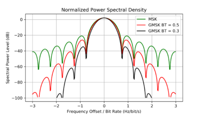
Gaussian minimum-shift keying, or GMSK, is similar to standard minimum-shift keying (MSK); however, the digital data stream is first shaped with a Gaussian filter before being applied to a frequency modulator, and typically has much narrower phase shift angles than most MSK modulation systems. This has the advantage of reducing sideband power, which in turn reduces out-of-band interference between signal carriers in adjacent frequency channels.[9]
However, the Gaussian filter increases the modulation memory in the system and causes intersymbol interference, making it more difficult to differentiate between different transmitted data values and requiring more complex channel equalization algorithms such as an adaptive equalizer at the receiver. GMSK has high spectral efficiency, but it needs a higher power level than QPSK, for instance, in order to reliably transmit the same amount of data. GMSK is most notably used in the Global System for Mobile Communications (GSM), in Bluetooth, in satellite communications,[10][11] and Automatic Identification System (AIS) for maritime navigation.
See also
- Constellation diagram used to examine the modulation in signal space (not time)
- Gaussian frequency-shift keying
References
- ↑ M.L Doelz and E.T. Heald, Minimum Shift Data Communication System, US Patent 2977417, 1958, http://www.freepatentsonline.com/2977417.html
- ↑ Anderson J. B., Aulin T., Sundberg C. E. Digital phase modulation. – Springer Science & Business Media, 2013. – p.49–50
- ↑ 3.0 3.1 Proakis, John G. (2001). Digital Communication (4 ed.). McGraw-Hill Inc.. pp. 196-199. https://archive.org/details/digitalcommunica00proa_354.
- ↑ Proakis J. G. Digital communications. 1995 //McGraw-Hill, New York. – p. 126-128
- ↑ Anderson J. B., Aulin T., Sundberg C. E. Digital phase modulation. – Springer Science & Business Media, 2013. – p. 49-50
- ↑ 6.0 6.1 Link Budget Analysis: Digital Modulation-Part 2-FSK (Atlanta RF)
- ↑ Haykin, S., 2001. Communication Systems, John Wiley&Sons. Inc. - p. 394
- ↑ Haykin, S., 2001. Communication Systems, John Wiley&Sons. Inc. - p. 398
- ↑ Poole, Ian. "What is GMSK Modulation - Gaussian Minimum Shift Keying". http://www.radio-electronics.com/info/rf-technology-design/pm-phase-modulation/what-is-gmsk-gaussian-minimum-shift-keying-tutorial.php.
- ↑ Rice, M., Oliphant, T., & Mcintire, W. (2007). Estimation techniques for GMSK using linear detectors in satellite communications. IEEE Transactions on Aerospace and Electronic Systems, 43(4).
- ↑ Wong, Yen F., et al. "An optimum space-to-ground communication concept for CubeSat platform utilizing NASA space network and near earth network." (2016).
- Subbarayan Pasupathy, Minimum Shift Keying: A Spectrally Efficient Modulation, IEEE Communications Magazine, 1979
- R. de Buda, Fast FSK Signals and their Demodulation, Can. Elec. Eng. J. Vol. 1, Number 1, 1976
- F. Amoroso, Pulse and Spectrum Manipulation in the Minimum (Frequency) Shift Keying (MSK) Format, IEEE Trans.
- "Appendix D – Digital Modulation and GMSK". University of Hull. 2001-03-13. http://www.emc.york.ac.uk/reports/linkpcp/appD.pdf.
- Link Budget Analysis: Digital Modulation-Part 2-FSK (Atlanta RF)
- Elnoubi, S., Chahine, S. A., & Abdallah, H. (2004, March). BER performance of GMSK in Nakagami fading channels. In Radio Science Conference, 2004. NRSC 2004. Proceedings of the Twenty-First National (pp. C13-1). IEEE.
- Feher, K. (1993, July). FQPSK: A modulation-power efficient RF amplification proposal for increased spectral efficiency and capacity GMSK and Π/4-QPSK compatible PHY standard. In IEEE 802.11 Wireless Access Methods Phys. Layer Spec. Doc.
 |
