Engineering:Octant (instrument)
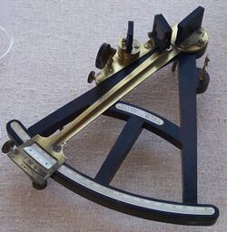
The octant, also called a reflecting quadrant, is a reflecting instrument used in navigation.
Etymology
The name octant derives from the Latin octans meaning eighth part of a circle, because the instrument's arc is one eighth of a circle.
Reflecting quadrant derives from the instrument using mirrors to reflect the path of light to the observer and, in doing so, doubles the angle measured. This allows the instrument to use a one-eighth of a turn to measure a quarter-turn or quadrant.
Origin of the octant
Newton's reflecting quadrant
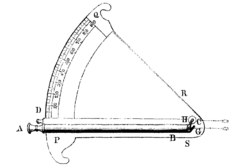
CD – index arm
G – horizon mirror
H – index mirror
PQ – graduated arc
Isaac Newton's reflecting quadrant was invented around 1699.[1] A detailed description of the instrument was given to Edmond Halley, but the description was not published until after Halley's death in 1742. It is not known why Halley did not publish the information during his life, as this prevented Newton from getting the credit for the invention that is generally given to John Hadley and Thomas Godfrey.
One copy of this instrument was constructed by Thomas Heath (instrument maker) and may have been shown in Heath's shop window prior to its being published by the Royal Society in 1742.[2]
Newton's instrument used two mirrors, but they were used in an arrangement somewhat different from the two mirrors found in modern octants and sextants. The diagram on the right shows the configuration of the instrument.[3]
The 45° arc of the instrument (PQ), was graduated with 90 divisions of a half-degree each. Each such division was subdivided into 60 parts and each part further divided into sixths. This results in the arc being marked in degrees, minutes and sixths of a minute (10 seconds). Thus the instrument could have readings interpolated to 5 seconds of arc. This fineness of graduation is only possible due to the large size of the instrument - the sighting telescope alone was three to four feet long.
A sighting telescope (AB), three or four feet long, was mounted along one side of the instrument. A horizon mirror was fixed at a 45° angle in front of the telescope's objective lens (G). This mirror was small enough to allow the observer to see the image in the mirror on one side and to see directly ahead on the other. The index arm (CD) held an index mirror (H), also at 45° to the edge of the index arm. The reflective sides of the two mirrors nominally faced each other, so that the image seen in the first mirror is that reflected from the second.
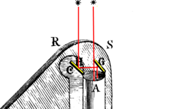
With the two mirrors parallel, the index reads 0°. The view through the telescope sees directly ahead on one side and the view from the mirror G sees the same image reflected from mirror H (see detail drawing to the right). When the index arm is moved from zero to a large value, the index mirror reflects an image that is in a direction away from the direct line of sight. As the index arm movement increases, the line of sight for the index mirror moves toward S (to the right in the detail image). This shows a slight deficiency with this mirror arrangement. The horizon mirror will block the view of the index mirror at angles approaching 90°.
The length of the sighting telescope seems remarkable, given the small size of the telescopes on modern instruments. This was likely Newton's choice of a way to reduce chromatic aberrations. Short–focal length telescopes, prior to the development of achromatic lenses, produced an objectionable degree of aberration, so much so that it could affect the perception of a star's position. Long focal lengths were the solution, and this telescope would likely have had both a long–focal length objective lens and a long–focal length eyepiece. This would decrease aberrations without excessive magnification.
The inventors of the octant
Two men independently developed the octant around 1730: John Hadley (1682–1744), an English mathematician, and Thomas Godfrey (1704–1749), a glazier in Philadelphia. While both have a legitimate and equal claim to the invention, Hadley generally gets the greater share of the credit. This reflects the central role that London and the Royal Society played in the history of scientific instruments in the eighteenth century.
Two others who created octants during this period were Caleb Smith, an English insurance broker with a strong interest in astronomy (in 1734), and Jean-Paul Fouchy, a mathematics professor and astronomer in France (in 1732).
Hadley's versions
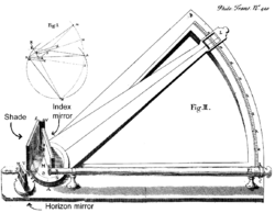
Hadley produced two versions of the reflecting quadrant. Only the second is well known and is the familiar octant.
Hadley's reflecting quadrant
Hadley's first reflecting quadrant was a simple device with a frame spanning a 45° arc. In the image at the right, from Hadley's article in the Philosophical Transactions of the Royal Society,[4] you can see the nature of his design. A small sighting telescope was mounted on the frame along one side. One large index mirror was mounted at the point of rotation of the index arm. A second, smaller horizon mirror was mounted on the frame in the line of sight of the telescope. The horizon mirror allows the observer to see the image of the index mirror in one half of the view and to see a distant object in the other half. A shade was mounted at the vertex of the instrument to allow one to observe a bright object. The shade pivots to allow it to move out of the way for stellar observations.
Observing through the telescope, the navigator would sight one object directly ahead. The second object would be seen by reflection in the horizon mirror. The light in the horizon mirror is reflected from the index mirror. By moving the index arm, the index mirror can be made to reveal any object up to 90° from the direct line of sight. When both objects are in the same view, aligning them together allows the navigator to measure the angular distance between them.
Very few of the original reflecting quadrant designs were ever produced. One, constructed by Baradelle, is in the collection of the Musée de la Marine, Paris.[5]
Hadley's octant
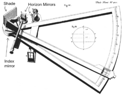
Hadley's second design had the form familiar to modern navigators. The image to the right, also taken from his Royal Society publication,[4] shows the details.
He placed an index mirror on the index arm. Two horizon mirrors were provided. The upper mirror, in the line of the sighting telescope, was small enough to allow the telescope to see directly ahead as well as seeing the reflected view. The reflected view was that of the light from the index mirror. As in the previous instrument, the arrangement of the mirrors allowed the observer to simultaneously see an object straight ahead and to see one reflected in the index mirror to the horizon mirror and then into the telescope. Moving the index arm allowed the navigator to see any object within 90° of the direct view.
The significant difference with this design was that the mirrors allowed the instrument to be held vertically rather than horizontally and it provided more room for configuring the mirrors without suffering from mutual interference.
The second horizon mirror was an interesting innovation. The telescope was removable. It could be remounted so that the telescope viewed the second horizon mirror from the opposite side of the frame. By mounting the two horizon mirrors at right angles to each other and permitting the movement of the telescope, the navigator could measure angles from 0 to 90° with one horizon mirror and from 90° to 180° with the other. This made the instrument very versatile. For unknown reasons, this feature was not implemented on octants in general use.
Comparing this instrument to the photo of a typical octant at the top of the article, one can see that the only significant differences in the more modern design are:
- The location of the horizon mirror and telescope or sighting pinnula is lower.
- The internal bracing of the frame is more central and robust.
- The position of the shades for the index mirror is in the path between the index and horizon mirrors rather than at the top of the instrument.
- Multiple shades are used to allow for different levels of shading.
- Separate shades are provided on the horizon mirror for sighting a low sun position with a very bright horizon.
- The second horizon mirror and accompanying alidade is not provided.
Smith's Astroscope
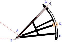
Caleb Smith, an English insurance broker with a strong interest in astronomy, had created an octant in 1734. He called it an Astroscope or Sea-Quadrant.[6] His used a fixed prism in addition to an index mirror to provide reflective elements. Prisms provide advantages over mirrors in an era when polished speculum metal mirrors were inferior and both the silvering of a mirror and the production of glass with flat, parallel surfaces was difficult.
In the drawing to the right, the horizon element (B) could be a mirror or a prism. On the index arm, the index mirror (A) rotated with the arm. A sighting telescope was mounted on the frame (C). The index did not use a vernier or other device at the scale (D). Smith called the instrument's index arm a label, in the manner of Elton for his mariner's quadrant.[7]
Various design elements of Smith's instrument made it inferior to Hadley's octant and it was not used significantly.[5] For example, one problem with the Astroscope was that angle of the observer's line of sight. By looking down, he had greater difficulty in observing than an orientation with his head in a normal orientation.
Advantages of the octant
The octant provided a number of advantages over previous instruments.
The sight was easy to align because the horizon and the star seem to move together as the ship pitched and rolled. This also created a situation where the error in observation was less dependent on the observer, as they could directly see both objects at once.
With the use of the manufacturing techniques available in the 18th century, the instruments were capable of reading very accurately. The size of the instruments was reduced with no loss of accuracy. An octant could be half the size of a Davis quadrant with no increase in error.
Using shades over the light paths, one could observe the sun directly, while moving the shades out of the light path allowed the navigator to observe faint stars. This made the instrument usable both night and day.
By 1780, the octant and sextant had almost completely displaced all previous navigational instruments.[5]
Production of the octant
Early octants were constructed primarily in wood, with later versions incorporating ivory and brass components. The earliest mirrors were polished metal, since the technology to produce silvered glass mirrors with flat, parallel surfaces was limited. As glass polishing techniques improved, glass mirrors began to be provided. These used coatings of mercury-containing tin amalgam; coatings of silver or aluminum were not available until the 19th century. The poor optical quality of the early polished speculum metal mirrors meant that telescopic sights were not practical. For that reason, most early octants employed a simple naked-eye sighting pinnula instead.

Early octants retained some of the features common to backstaves, such as transversals on the scale. However, as engraved, they showed the instrument to have an apparent accuracy of only two minutes of arc while the backstaff appeared to be accurate to one minute. The use of the vernier scale allowed the scale to be read to one minute, so improved the marketability of the instrument. This and the ease in making verniers compared to transversals, lead to adoption of the vernier on octants produced later in the 18th century.[8]
Octants were produced in large numbers. In wood and ivory, their relatively low price compared to an all-brass sextant made them a popular instrument. The design was standardized with many manufacturers using the identical frame style and components. Different shops could make different components, with woodworkers specializing in frames and others in the brass components. For example, Spencer, Browning and Rust, a manufacturer of scientific instruments in England from 1787 to 1840 (operating as Spencer, Browning and Co. after 1840) used a Ramsden dividing engine to produce graduated scales in ivory. These were widely used by others and the SBR initials could be found on octants from many other manufacturers.[9]
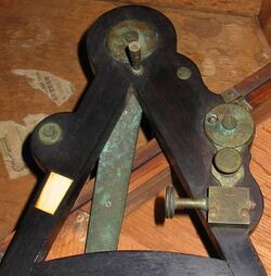
Examples of these very similar octants are in the photos in this article. The image at the top is essentially the same instrument as the one in the detail photos. However, they are from two different instrument makers - the upper is labelled Crichton - London, Sold by J Berry Aberdeen while the detail images are of an instrument from Spencer, Browning & Co. London. The only obvious difference is the presence of horizon shades on the Crichton octant that are not on the other.

These octants were available with many options. A basic octant with graduations directly on the wood frame were least expensive. These dispensed with a telescopic sight, using a single- or double-holed sighting pinnula instead. Ivory scales would increase the price, as would the use of a brass index arm or a vernier.
Demise of the octant
In 1767 the first edition of The Nautical Almanac tabulated lunar distances, enabling navigators to find the current time from the angle between the Sun and the Moon. This angle is sometimes larger than 90°, and thus not possible to measure with an octant. For that reason, Admiral John Campbell, who conducted shipboard experiments with the lunar distance method, suggested a larger instrument and the sextant was developed.[10]
From that time onward, the sextant was the instrument that experienced significant development and improvements and was the instrument of choice for naval navigators. The octant continued to be produced well into the 19th century, though it was generally a less accurate and less expensive instrument. The lower price of the octant, including versions without telescope, made it a practical instrument for ships in the merchant and fishing fleets.
One common practice among navigators up to the late nineteenth century was to use both a sextant and an octant. The sextant was used with great care and only for lunars, while the octant was used for routine meridional altitude measurements of the Sun every day.[7] This protected the very accurate and pricier sextant, while using the more affordable octant where it performs well.
Bubble octant
From the early 1930s through the end of the 1950s, several types of civilian and military bubble octant instruments were produced for use aboard aircraft.[11] All were fitted with an artificial horizon in the form of a bubble, which was centered to align the horizon for a navigator flying thousands of feet above the Earth; some had recording features.[12]
Use and adjustment
Use and adjustment of the octant is essentially identical to the navigator's sextant.
Other reflecting instruments
Hadley's was not the first reflecting quadrant. Robert Hooke invented a reflecting quadrant in 1684[13] and had written about the concept as early as 1666.[14] Hooke's was a single-reflecting instrument.[14] Other octants were developed by Jean-Paul Fouchy and Caleb Smith in the early 1730s, however, these did not become significant in the history of navigation instruments.
See also
References
- ↑ Newton, Isaac (October–November 1742). "A true Copy of a Paper found, in the Hand Writing of Sir Isaac Newton, among the Papers of the late Dr. Halley, containing a Description of an Instrument for observing the Moon's distance from the Fixt Stars at Sea". Philosophical Transactions of the Royal Society 42 (465): 155–156 and plate. doi:10.1098/rstl.1742.0039. Bibcode: 1742RSPT...42..155N. https://books.google.com/books?id=Q8FeAAAAcAAJ&pg=155. "By this instrument the distance of the moon from any fixed star is thus observed; view the star through the perspicil by the direct light, and the moon by the reflexed, (or on the contrary;) and turn the index till the star touch the limb of the moon, and the index shall show on the brass limb of the instrument the distance of the star from the moon's limb; and though the instrument shake by the motion of the ship at sea, yet the moon and star will move together as if they did really touch one another in the heavens; so that an observation may be made as exactly at sea as at land. And by the same instrument, may be observed exactly the altitudes of the moon and stars, by bringing them to the horizon; and thereby the latitude and times of observation may be determined more exactly than by the ways now in use.". Vol. 42 at archive.org
- ↑ Taylor, E. G. R. (1971). The Haven-finding Art: A History of Navigation from Odysseus to Captain Cook. London: Hollis & Carter. ISBN 0-370-01347-6.
- ↑ Brewster, David (1855). Memoirs of the Life, Writings, and Discoveries of Sir Isaac Newton. 1. Edinburgh: Thomas Constable & Co.. pp. 239–242. https://archive.org/details/memoirslifewrit03brewgoog. excerpt
- ↑ 4.0 4.1 Hadley, John (August–September 1731). "The Description of a new Instrument for taking Angles". Philosophical Transactions of the Royal Society 37 (420): 147–157 and plates. doi:10.1098/rstl.1731.0025. https://books.google.com/books?id=CcVeAAAAcAAJ&pg=147.
- ↑ 5.0 5.1 5.2 Daumas, Maurice, Scientific Instruments of the Seventeenth and Eighteenth Centuries and Their Makers, Portman Books, London 1989 ISBN 978-0-7134-0727-3
- ↑ Bedini, Silvio (September 1997). "History Corner: Benjamin King of Newport, R.I.-Part II". Professional Surveyor Magazine 17 (6). http://www.profsurv.com/archive.php?issue=17&article=184.
- ↑ 7.0 7.1 May, William Edward, A History of Marine Navigation, G. T. Foulis & Co. Ltd., Henley-on-Thames, Oxfordshire, 1973, ISBN 0-85429-143-1
- ↑ Bennett, Jim, "Catadioptrics and commerce in eighteenth-century London", in History of Science, vol xliv, 2006, pages 247-277.
- ↑ Harriet Wynter and Anthony Turner, Scientific Instruments, Studio Vista, 1975, ISBN 0-289-70403-0
- ↑ Gerard L'E. Turner, Nineteenth Century Scientific Instruments, Sotheby Publications, 1983, ISBN 0-85667-170-3
- ↑ Brink, Randall, Lost Star: The Search for Amelia Earhart, W. W. Norton & Company, (1994), ISBN 0-393-02683-3, ISBN 978-0-393-02683-2, p. 32
- ↑ Cardoza, Rod (n.d.). "Evolution of the Sextant". http://home.earthlink.net/~nbrass1/cardart.htm.
- ↑ "Chronology of Robert Hooke's life". http://www.roberthooke.org.uk/chronolo.htm.
- ↑ 14.0 14.1 Charles H. Cotter The Mariner's Sextant and the Royal Society; Notes and Records of the Royal Society of London, Vol. 33, No. 1 (August 1978), pp. 23-36.
External links
 |
