Engineering:Polarization-maintaining optical fiber

In fiber optics, polarization-maintaining optical fiber (PMF or PM fiber) is a single-mode optical fiber in which linearly polarized light, if properly launched into the fiber, maintains a linear polarization during propagation, exiting the fiber in a specific linear polarization state; there is little or no cross-coupling of optical power between the two polarization modes. Such fiber is used in special applications where preserving polarization is essential.
Polarization crosstalk
In an ordinary (non-polarization-maintaining) fiber, two polarization modes (say vertical and horizontal polarization) have the same nominal phase velocity due to the fiber's circular symmetry. However tiny amounts of random birefringence in such a fiber, or bending in the fiber, will cause a tiny amount of crosstalk from the vertical to the horizontal polarization mode. And since even a short portion of fiber, over which a tiny coupling coefficient may apply, is many thousands of wavelengths long, even that small coupling between the two polarization modes, applied coherently, can lead to a large power transfer to the horizontal mode, completely changing the wave's net state of polarization. Since that coupling coefficient was unintended and a result of arbitrary stress or bending applied to fiber, the output state of polarization will itself be random, and will vary as those stresses or bends vary; it will also vary with wavelength.
Principle of operation
Polarization-maintaining fibers work by intentionally introducing a systematic linear birefringence in the fiber, so that there are two well defined polarization modes which propagate along the fiber with very distinct phase velocities. The beat length Lb of such a fiber (for a particular wavelength) is the distance (typically a few millimeters) over which the wave in one mode will experience an additional delay of one wavelength compared to the other polarization mode. Thus a length Lb /2 of such fiber is equivalent to a half-wave plate. Now consider that there might be a random coupling between the two polarization states over a significant length of such fiber. At point 0 along the fiber, the wave in polarization mode 1 induces an amplitude into mode 2 at some phase. However at point 1/2 Lb along the fiber, the same coupling coefficient between the polarization modes induces an amplitude into mode 2 which is now 180 degrees out of phase with the wave coupled at point zero, leading to cancellation. At point Lb along the fiber the coupling is again in the original phase, but at 3/2 Lb it is again out of phase and so on. The possibility of coherent addition of wave amplitudes through crosstalk over distances much larger than Lb is thus eliminated. Most of the wave's power remains in the original polarization mode, and exits the fiber in that mode's polarization as it is oriented at the fiber end. Optical fiber connectors used for PM fibers are specially keyed so that the two polarization modes are aligned and exit in a specific orientation.
Note that a polarization-maintaining fiber does not polarize light as a polarizer does. Rather, PM fiber maintains the linear polarization of linearly polarized light provided that it is launched into the fiber aligned with one of the fiber's polarization modes. Launching linearly polarized light into the fiber at a different angle will excite both polarization modes, conducting the same wave at slightly different phase velocities. At most points along the fiber the net polarization will be an elliptically polarized state, with a return to the original polarization state after an integer number of beat lengths. Consequently, if visible laser light is launched into the fiber exciting both polarization modes, scattering of propagating light viewed from the side, is observed with a light and dark pattern periodic over each beat length, since scattering is preferentially perpendicular to the polarization direction.
Designs
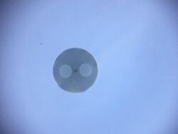
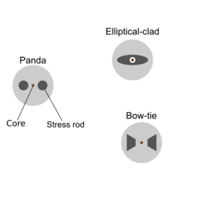
Several different designs are used to create birefringence in a fiber.[1] The fiber may be geometrically asymmetric or have a refractive index profile which is asymmetric such as the design using an elliptical cladding as shown in the diagram. Alternatively, stress permanently induced in the fiber will produce stress birefringence; this may be accomplished using rods of another material included within the cladding. Several different shapes of rod are used, and the resulting fiber is sold under brand names such as "PANDA" and "Bow-tie". ("PANDA" refers to the resemblance of the fiber's cross-section to the face of a panda, and is also an acronym for "Polarization-maintaining AND Absorption-reducing".)
It is possible to create a circularly birefringent optical fiber just using an ordinary (circularly symmetric) single-mode fiber and twisting it, thus creating internal torsional stress. That causes the phase velocity of right and left hand circular polarizations to significantly differ. Thus the two circular polarizations propagate with little crosstalk in between them
Applications
Polarization-maintaining optical fibers are used in special applications, such as in fiber optic sensing, interferometry and quantum key distribution. They are also commonly used in telecommunications for the connection between a source laser and a modulator, since the modulator requires polarized light as input. They are rarely used for long-distance transmission, because PM fiber is expensive and has higher attenuation than single-mode fiber. Another important application is fiber-optic gyroscopes, which are widely used in the aerospace industry.
The output of a PM fiber is typically characterized by its polarization extinction ratio (PER)—the ratio of correctly to incorrectly polarized light, expressed in decibels. The quality of PM patchcords and pigtails can be characterized with a PER meter. Good PM fibers have extinction ratios in excess of 20 dB.
References
- ↑ Carter, Adrian; Samson, Bryce (August 2004). "PANDA-style fibers move beyond telecom". Laser Focus World.
- MIL-STD-2196
External links
- Fujikura's PANDA Fiber Specs for the most common type of PM fiber
- Polarization Crosstalk in PM Fiber
 |


