Engineering:Regenerative heat exchanger
A regenerative heat exchanger, or more commonly a regenerator, is a type of heat exchanger where heat from the hot fluid is intermittently stored in a thermal storage medium before it is transferred to the cold fluid. To accomplish this the hot fluid is brought into contact with the heat storage medium, then the fluid is displaced with the cold fluid, which absorbs the heat.[1]
In regenerative heat exchangers, the fluid on either side of the heat exchanger can be the same fluid. The fluid may go through an external processing step, and then it is flowed back through the heat exchanger in the opposite direction for further processing. Usually the application will use this process cyclically or repetitively.
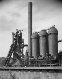
Regenerative heating was one of the most important technologies developed during the Industrial Revolution when it was used in the hot blast process on blast furnaces.[2] It was later used in glass melting furnaces and steel making, to increase the efficiency of open hearth furnaces, and in high pressure boilers and chemical and other applications, where it continues to be important today.
History

The first regenerator was invented by Rev. Robert Stirling in 1816, and is also found as a component of some examples of his Stirling engine. The simplest Stirling engines, including most models, use the walls of the cylinder and displacer as a rudimentary regenerator, which is simpler and cheaper to construct but far less efficient.
Later applications included the blast furnace process known as hot blast and the open hearth furnace also called Siemens regenerative furnace (which was used for making glass), where the hot exhaust gases from combustion are passed through firebrick regenerative chambers, which are thus heated. The flow is then reversed, so that the heated bricks preheat the fuel.
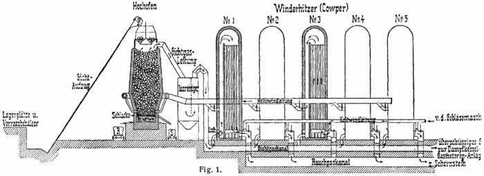
Edward Alfred Cowper applied the regeneration principle to blast furnaces, in the form of the "Cowper stove", patented in 1857.[3] This is almost invariably used with blast furnaces to this day.

Types of regenerators
Regenerators exchange heat from one process fluid to an intermediate solid heat storage medium, then that medium exchanges heat with a second process fluid flow. The two flows are either separated in time, alternately circulating through the storage medium, or are separated in space and the heat storage medium is moved between the two flows.
In rotary regenerators, or thermal wheels, the heat storage "matrix" in the form of a wheel or drum, that rotates continuously through two counter-flowing streams of fluid. In this way, the two streams are mostly separated. Only one stream flows through each section of the matrix at a time; however, over the course of a rotation, both streams eventually flow through all sections of the matrix in succession. The heat storage medium can be a relatively fine-grained set of metal plates or wire mesh, made of some resistant alloy or coated to resist chemical attack by the process fluids, or made of ceramics in high temperature applications. A large amount of heat transfer area can be provided in each unit volume of the rotary regenerator, compared to a shell-and-tube heat exchanger - up to 1000 square feet of surface can be contained in each cubic foot of regenerator matrix, compared to about 30 square feet in each cubic foot of a shell-and-tube exchanger.[4]
Each portion of the matrix will be nearly isothermal, since the rotation is perpendicular to both the temperature gradient and flow direction, and not through them. The two fluid streams flow counter-current. The fluid temperatures vary across the flow area; however the local stream temperatures are not a function of time. The seals between the two streams are not perfect, so some cross contamination will occur. The allowable pressure level of a rotary regenerator is relatively low, compared to heat exchangers.


In a fixed matrix regenerator, a single fluid stream has cyclical, reversible flow; it is said to flow "counter-current". This regenerator may be part of a valveless system, such as a Stirling engine. In another configuration, the fluid is ducted through valves to different matrices in alternate operating periods resulting in outlet temperatures that vary with time. For example, a blast furnace may have several "stoves" or "checkers" full of refractory fire brick. The hot gas from the furnace is ducted through the brickwork for some interval, say one hour, until the brick reaches a high temperature. Valves then operate and switch the cold intake air through the brick, recovering the heat for use in the furnace. Practical installations will have multiple stoves and arrangements of valves to gradually transfer flow between a "hot" stove and an adjacent "cold" stove, so that the variations in the outlet air temperature are reduced.[5]
Another type of regenerator is called a micro scale regenerative heat exchanger. It has a multilayer grating structure in which each layer is offset from the adjacent layer by half a cell which has an opening along both axes perpendicular to the flow axis. Each layer is a composite structure of two sublayers, one of a high thermal conductivity material and another of a low thermal conductivity material. When a hot fluid flows through the cell, heat from the fluid is transferred to the cell wells, and stored there. When the fluid flow reverses direction, heat is transferred from the cell walls back to the fluid.
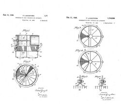
A third type of regenerator is called a "Rothemühle" regenerator. This type has a fixed matrix in a disk shape, and streams of fluid are ducted through rotating hoods. The Rothemühle regenerator is used as an air preheater in power generating plants. The thermal design of this regenerator is the same as of other types of regenerators. [citation needed]
Biology
The nose and throat work as regenerative heat exchangers during breathing. The cooler air coming in is warmed, so that it reaches the lungs as warm air. On the way back out, this warmed air deposits much of its heat back onto the sides of the nasal passages, so that these passages are then ready to warm the next batch of air coming in. Some animals, including humans, have curled sheets of bone inside the nose called nasal turbinates to increase the surface area for heat exchange.[citation needed]
Cryogenics
Regenerative heat exchangers are made up of materials with high volumetric heat capacity and low thermal conductivity in the longitudinal (flow) direction. At cryogenic (very low) temperatures around 20 K, the specific heat of metals is low, and so a regenerator must be larger for a given heat load.[citation needed]
Advantages of regenerators
The advantages of a regenerator over a recuperating (counter-flowing) heat exchanger is that it has a much higher surface area for a given volume, which provides a reduced exchanger volume for a given energy density, effectiveness and pressure drop. This makes a regenerator more economical in terms of materials and manufacturing, compared to an equivalent recuperator.[citation needed]
The design of inlet and outlet headers used to distribute hot and cold fluids in the matrix is much simpler in counter flow regenerators than recuperators. The reason behind this is that both streams flow in different sections for a rotary regenerator and one fluid enters and leaves one matrix at a time in a fixed-matrix regenerator. Furthermore, flow sectors for hot and cold fluids in rotary regenerators can be designed to optimize pressure drop in the fluids. The matrix surfaces of regenerators also have self-cleaning characteristics, reducing fluid-side fouling and corrosion. Finally properties such as small surface density and counter-flow arrangement of regenerators make it ideal for gas-gas heat exchange applications requiring effectiveness exceeding 85%. The heat transfer coefficient is much lower for gases than for liquids, thus the enormous surface area in a regenerator greatly increases heat transfer.[citation needed]
Disadvantages of regenerators
The major disadvantage of rotary and fixed-matrix regenerators is that there is always some mixing of the fluid streams, and they can not be completely separated. There is an unavoidable carryover of a small fraction of one fluid stream into the other. In the rotary regenerator, the carryover fluid is trapped inside the radial seal and in the matrix, and in a fixed-matrix regenerator, the carryover fluid is the fluid that remains in the void volume of the matrix. This small fraction will mix with the other stream in the following half-cycle. Therefore, rotary and fixed-matrix regenerators are only used when it is acceptable for the two fluid streams to be mixed. Mixed flow is common for gas-to-gas heat and/or energy transfer applications, and less common in liquid or phase-changing fluids since fluid contamination is often prohibited with liquid flows.[citation needed]
The constant heating and cooling that takes place in regenerative heat exchangers puts a lot of stress on the components of the heat exchanger, which can cause cracking or breakdown of materials.[citation needed]
See also
- Countercurrent exchange
- Economizer
- Heat exchanger
- Hot blast
- Recuperator
- desalination – some thermal desalination plants use regenerative heat exchangers
- Thermal wheel, a regenerative heat exchanger where the heated medium is rotated continuously between the two gasflows.
References
- ↑ Regenerative heat exchangers
- ↑ Landes, David S. (1969). The Unbound Prometheus: Technological Change and Industrial Development in Western Europe from 1750 to the Present. Cambridge, New York: Press Syndicate of the University of Cambridge. p. 92. ISBN 0-521-09418-6.
- ↑ (in en) Chronological and Descriptive Index of Patents Applied for and Patents Granted, Containing the Abridgements of Provisional and Complete Specifications. 1858. https://books.google.com/books?id=zXMyAQAAIAAJ&q=edward+alfred+cowper.
- ↑ John J. McKetta Jr (ed.), Heat Transfer Design Methods, CRC Press, 1991, ISBN 0849306655, pages 101-103
- ↑ Ramesh K. Shah, Dusan P. Sekulic Fundamentals of Heat Exchanger Design, John Wiley & Sons, 2003 ISBN 0471321710, page 55
Bibliography
- Butz, J. S., Jr. (July 1962). "Engine economy through regeneration". Flying 71 (1): 44–45, 89–91. ISSN 0015-4806. https://books.google.com/books?id=bHZ-ngYi4zUC&pg=PA44.
- John H. Glenn Research Center (August 2006). "Microscale regenerative heat exchanger". NASA Tech Briefs 30 (8). ISSN 1049-3522. OCLC 102235244. http://www.techbriefs.com/content/view/61/34/.
- https://books.google.com/books?id=beSXNAZblWQC&pg=PA8&dq=fluid+heat+exchangers&sig=v3NF11puSFyQiUfPV2VbWjOEHik#PPA51,M1
 |
