Engineering:SEPTA's 25 Hz traction power system
The Southeastern Pennsylvania Transportation Authority (SEPTA) operates a 25 Hz traction power system in the vicinity of Philadelphia, that it inherited from the Reading Company. This system is separate from, but similar to, the system built by the Pennsylvania Railroad (PRR), which is now operated by Amtrak. SEPTA's trains can run over either system because the voltage and frequency presented to the locomotive are essentially identical. However, the ex-Reading system is not electrically connected to the ex-PRR system.
SEPTA owns all of the substations described herein. Although SEPTA also owns former PRR substations along the Media/Wawa Line and the Chestnut Hill West Line, as well as a new substation just north of 30th Street Station, those facilities are electrically part of Amtrak's 25 Hz traction power system.
History
The Reading Company electrified its lines between Reading Terminal in Philadelphia, Pennsylvania, and Norristown, Doylestown, Chestnut Hill, Hatboro and West Trenton in 1931. The electrification was extended to include the Fox Chase Line in September 1966. Electrification was again extended from Hatboro to Warminster in the early 1970s.[1][page needed]
The Reading's system used catenary electrified at 12 kV 25 Hz like the competing Pennsylvania Railroad's 1915 initial electrification and 1930s mainline expansion. Unlike the PRR's system, which included multiple power sources and an extensive high-voltage transmission network, the Reading's electrification was supplied solely by the rotary converter station at Wayne Junction. Although ownership and operation of the system has changed, the system has remained essentially unchanged with the exception of the replacement of the rotary converter station at Wayne Junction with a solid-state cycloconverter in 1986.
Transmission system architecture
The Reading electrification system was designed for suburban MU operations and did not have to support the main line passenger or through freight operations of the rival Pennsylvania Railroad. While a complex system of high-voltage transmission lines was not necessary, the system was large enough to require the use of distribution feeders from the 25 Hz power supply at Wayne Junction. The feeders were set at 24 kV, double the traction voltage. Most of the rail lines would carry one or two feeders attached to the top of the catenary support masts. These 24 kV substation feeders can be distinguished from 12 kV traction feeders by the use of four-segment insulators as opposed to three-segment ones.

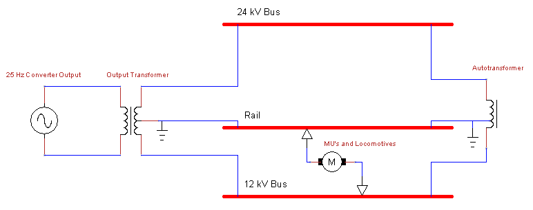
The 24 kV lines feed a network of 11 substations (12 including the Wayne Junction switchyard) located every 8 to 10 miles (13 to 16 km) along the electrified rail lines. Most branches are short enough to only require a single substation near the end of the line, but the Main and West Trenton lines are long enough to require intermediate substations. At each substation the 24 kV feeders are fed through autotransformers to be reduced to the traction voltage of 12 kV, which is then passed through circuit breakers before being fed into the overhead catenary wires.
Power is transmitted, effectively, at 36 kV because the 24 kV and 12 kV components are 180° out of phase. This design has several advantages over the PRR's more traditional transmission and distribution scheme. The highest voltage, with respect to ground, within the system is 24 kV. This is significantly less than the 69 kV seen in the PRR's system, which required much larger 80 feet (24 m) towers and larger insulators and transformers. On a small system such as the Reading's, transmission infrastructure of this scale was unnecessary. Secondly, the system uses the 12 kV catenary wire for both transmission and distribution. This dual use of the catenary wire allows performing both functions with only two wires. The PRR's system in contrast required three wires: two for the single phase 138 kV transmission component and one for the 12 kV catenary feeder. In both systems, the rail is used as a return path for traction current.
Static frequency converters
All 25 Hz power on the ex-Reading system is generated at the Wayne Junction static converter plant. This plant was built between 1985 and 1990 and consists of three 15 MVA solid-state, cycloconverter-based modules. The system was built by ASEA and is similar technically to the converter later installed at Amtrak's Jericho Park converter.
The inverters replaced two ca. 1928 Westinghouse Electric motor generators that were each rated at 21.4 MVA. The capability also formerly existed to supply power from PECO Energy's Somerset Substation, which had three motor-generators normally used to supply the Pennsylvania Railroad's electrification system. This capability has been removed, as have the Somerset motor-generators. The ex-Reading system now operates completely independently from Amtrak's power system.
Wayne Junction receives 230 kV 60 Hz power from two redundant lines that connect to PECO substations at Waneeta, Tabor and Pulaski. Two 60 MVA 230/13.2 kV transformers reduce voltage for the static frequency converters. Cross-ties allow removing portions of the supply system from service for maintenance.
In March 2015 a contract worth $4,656,321 was awarded to STV Incorporated, for the provision of architectural and engineering services for the rehabilitation of static frequency converters at Wayne Junction, with services to be performed over a period of 60 months scheduled to commence in April 2015 (per Proposal No. 14-233-JHC).[3]
Substations
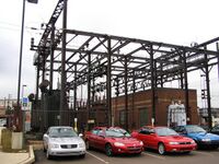
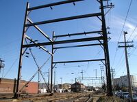
Each of the former Reading Railroad substations was equipped with transformers and circuit breakers from American Brown Boveri. Most transformers are rated to supply about 2 MVA of power each (a few 4 MVA transformers exist). Each substation also contained a number of oil-filled circuit breakers to disconnect both the 12 kV and 24 kV lines under load. The larger substations also have a small equipment and maintenance building to house any control equipment or secondary transformers for generating the 100 Hz signal power.
Replacement and renewal
Due to the robustness and simplicity of the components, until 2010 all the SEPTA substations were equipped with their original equipment, then approaching 80 years in service.
Callowhill / Fairmount
Callowhill substation was the first targeted for replacement, to eliminate the need to maintain the overhead wires over the abandoned Reading Viaduct rail line as feeders to the active tracks. Its replacement, Fairmount substation, was commissioned in the 3rd quarter of 2010,[4] featuring two 12/24 kV 25 Hz, single-phase 5 MVA autotransformers as well as trolley breakers and other switchgear.[5]
Norristown
Norristown substation received new transformers, trolley breakers, feeders, substation switchgear, protective relaying and a structural overhaul in a stimulus project.[6]
Wayne Junction
In July 2012, the US Department of Transportation awarded SEPTA a $12.8 million Tiger IV grant to help refurbish Wayne Junction Substation.[7] In the words of SEPTA General Manager Joseph M. Casey, "We intend to use these resources to replace equipment that should be on display in a museum of transit history."
The grant was announced at ceremony at the substation which was attended by Transportation Secretary Ray LaHood, who said "It's not the sexiest, it's not the prettiest, but it's one of the most important projects."[8]
Renewal of Wayne Junction's three static frequency converters is expected to occur during the 2010s, in three stages in order to maintain redundancy. A fourth converter is to be added for system security.[9][S 1]
In October 2014 SEPTA requested interested contractors to submit bids for the rehabilitation of the static frequency converters at Wayne Junction.[10]
Ambler
In September 2014 SEPTA requested interested contractors to submit bids for the rehabilitation of Ambler substation.[11] In October 2014 SEPTA awarded a $7.99 million contract to Carr & Duff, Inc.[12] for the work.[13]
Lansdale
On October 31, 2016, one of the substation's two main transformers burned out, and was replaced ahead of schedule a week later with one of the new transformers already on hand for the substation renewals at both Lansdale and Ambler.[14]
Doylestown
In the 1990s a fire at the Doylestown substation rendered it inoperable. Until the substation was repaired in 2013, the Doylestown Branch east of Lansdale had to be powered exclusively from the Lansdale substation. This "single-end feeding" of a 10-mile (16 km) section of track limited the number of MUs that could run simultaneously on the branch and also limited their maximum speed and acceleration.
The substation received a new 12/24 kV autotransformer in April 2015.[15]
Other substations
With the passage of a source of dedicated transportation funding by the Commonwealth of Pennsylvania, SEPTA announced in December 2013 a capital budget plan that includes renewal or replacement of all remaining former Reading substations, in five phases. The first phase involves replacement of Jenkintown substation and the renewal of Ambler substation's active components, projects for which final design had been completed by the end of 2013.[9][16]
In November 2014 SEPTA requested interested contractors to submit bids for the rehabilitation of four substations (Lansdale, Bethayres, Chestnut Hill East and Hatboro).[17] The engineering design work is expected to take two years, and the construction a further three years.
SEPTA also plans to build a new substation near Woodbourne station by Fall 2020, as the distance between Neshaminy Falls and Yardley substations is nearly twice the optimal 5-mile (8.0 km) distance between substations on a 12 kV 25 Hz system.[S 2]
| Name | Transformers | Line Served | Coordinates | Notes |
|---|---|---|---|---|
| Ambler | 1 | Main Line | [ ⚑ ] 40°09′02″N 75°13′21″W / 40.15056°N 75.2225°W | Designed for two transformers, but only one was ever installed. Renewal designed and funded[16] Scheduled to be renewed by Summer 2016.[S 3] |
| Bethayres | 1 | West Trenton Line | [ ⚑ ] 40°06′57″N 75°04′07″W / 40.11583°N 75.06861°W | Scheduled to be renewed by Spring 2018.[S 4] |
| Callowhill (Reading Terminal) |
2 | Main Line | [ ⚑ ] 39°57′31″N 75°09′26″W / 39.95861°N 75.15722°W | Replaced by Fairmount substation in 2010. Abandoned. |
| Chestnut Hill East | 1 | Chestnut Hill East Line | [ ⚑ ] 40°04′51″N 75°12′20″W / 40.08083°N 75.20556°W | Originally had 2 transformers. Scheduled to be renewed by Summer 2018.[S 5] |
| Doylestown | 1 | Doylestown Branch | [ ⚑ ] 40°18′09″N 75°08′04″W / 40.3025°N 75.13444°W | Renewed Spring 2015.[S 6] |
| Fairmount | 2 | Main Line | [ ⚑ ] 39°57′55″N 75°09′07″W / 39.96528°N 75.15194°W | Built 2010, replaced Callowhill Substation. |
| Hatboro | 1 | Warminster Line | [ ⚑ ] 40°10′30″N 75°06′11″W / 40.175°N 75.10306°W | Scheduled to be renewed by Winter 2020.[S 7] |
| Jenkintown | 2 | West Trenton and Main Lines | [ ⚑ ] 40°05′50″N 75°08′17″W / 40.09722°N 75.13806°W | Replacement under construction; scheduled completion Fall 2016.[S 8] |
| Lansdale | 2 | Main Line | [ ⚑ ] 40°14′38″N 75°17′07″W / 40.24389°N 75.28528°W | Scheduled to be renewed by Summer 2017.[S 9] |
| Neshaminy Falls | 2 | West Trenton Line | [ ⚑ ] 40°08′45″N 74°57′54″W / 40.14583°N 74.965°W | Scheduled to be renewed by Summer 2019.[S 10] |
| Norristown | 2 | Manayunk/Norristown Line | [ ⚑ ] 40°06′48″N 75°20′48″W / 40.11333°N 75.34667°W | Feeders re-oriented 180° in 1970 for line relocation due to Dannehower Bridge (US 202) construction. All substation components replaced 2012. |
| Wayne Junction | 3 (step-up) | All | [ ⚑ ] 40°01′31″N 75°09′23″W / 40.02528°N 75.15639°W | Design work is being undertaken to renew the electrical equipment at this site [7] |
| Woodbourne | 2 | West Trenton Line | [ ⚑ ] 40°11′34″N 74°53′21″W / 40.19278°N 74.88917°W | New substation scheduled to be built by Fall 2020.[S 2] |
| Yardley | 2 | West Trenton Line | [ ⚑ ] 40°14′03″N 74°49′55″W / 40.23417°N 74.83194°W | Scheduled to be renewed by Summer 2019.[S 11] |
See also
Footnotes
General
- ↑ Kneschke et al. (1995).
- ↑ Kneschke et al. (1995), p. 80.
- ↑ SEPTA (March 26, 2015). "Minutes of Regular Board Meeting (March 2015)". http://www4.septa.org/about/board/pdf/minutes%203-15.pdf.
- ↑ "Regional Rail Substation Improvements". SEPTA Fiscal Year 2010 Capital Budget & Fiscal Years 2010-2021 Capital Program. SEPTA. http://www.septa.org/reports/pdf/capbudget10.pdf.
- ↑ "Fairmount Substation and 30th Street Switching Station". Gannett Fleming Transit & Rail Systems. http://www.gftransitrail.com/projects/fairmountsubstation.htm.
- ↑ "Norristown Power Substation Overhaul P2-2A". SEPTA Stimulus Project Information. SEPTA. http://www.septa.org/stimulus/projects/rail/nor/p2-2a/index.shtml.
- ↑ 7.0 7.1 "Wayne Junction Substation Update". Southeastern Pennsylvania Transportation Authority. http://www.septa.org/service/rail/wayne-junction-update.html.
- ↑ Quinn, Amy Z. (July 11, 2012). "Unsexy, but critically needed, replacement coming for Wayne Junction Substation". http://www.newsworks.org/index.php/component/flexicontent/item/41297-wayne-junction-announcement&Itemid=18.
- ↑ 9.0 9.1 SEPTA. "Railroad Substation Program". Proposed Capital Plan: "Catching Up". Southeastern Pennsylvania Transportation Authority. http://www.septa.org/media/releases/2013/2013-12-19-capital-improvement-plan.pdf.
- ↑ "Bids | Page | SEPTA". http://www.septa.org/business/bid/100k/detail/14-223-JHC.html.
- ↑ "Bids | Page | SEPTA". http://www.septa.org/business/bid/100k/detail/14-156-JAB.html.
- ↑ "Carr and Duff, Inc.". http://www.carrduff.com.
- ↑ http://www.septa.org/business/bid/results/detail/pdf/r14-156-JAB.pdf [bare URL PDF]
- ↑ Almeida, John P. (November 20, 2016). "SEPTA Lansdale Parking Garage Lansdale PA November 19 2016 [6th photo and caption"]. The Philadelphia Chapter of the National Railway Historical Society. http://www.trainweb.org/phillynrhs/RPOTW161120.html.
- ↑ Almeida, John P. (June 21, 2015). "Out with the old: SEPTA transformer replacement Doylestown PA April 12 2015". The Philadelphia Chapter of the National Railway Historical Society. http://www.trainweb.org/phillynrhs/RPOTW150621.html.
- ↑ 16.0 16.1 "SEPTA Projects Funded Under Senate Bill 1". PennDOT Decade of Investment. Pennsylvania Department of Transportation. http://www.dotdecade.pa.gov/doi/pdf/SEPTA-Senate-Plan.pdf.
- ↑ SEPTA (November 2014). "A&E Services for Rehabilitation of Regional Railroad Division Substations (Proposal Number 14-268-JHC)". http://www.septa.org/business/bid/100k/detail/14-268-JHC.html.
Rebuilding for the Future (Substation Program)
- ↑ SEPTA. "Wayne Junction Static Frequency Converters (Main Regional Rail Line)". Southeastern Pennsylvania Transportation Authority. http://septa.org/rebuilding/substation/wayne-junction.html.
- ↑ 2.0 2.1 SEPTA. "Woodbourne Substation (West Trenton Line)". Southeastern Pennsylvania Transportation Authority. http://septa.org/rebuilding/substation/woodbourne.html.
- ↑ SEPTA. "Ambler Substation (Lansdale/Doylestown Regional Rail Line)". Southeastern Pennsylvania Transportation Authority. http://septa.org/rebuilding/substation/ambler.html.
- ↑ SEPTA. "Bethayres Substation (West Trenton Regional Rail Line)". Southeastern Pennsylvania Transportation Authority. http://septa.org/rebuilding/substation/bethayres.html.
- ↑ SEPTA. "Chestnut Hill East Substation (Chestnut Hill East Regional Rail Line)". Southeastern Pennsylvania Transportation Authority. http://septa.org/rebuilding/substation/che.html.
- ↑ SEPTA. "Doylestown Substation". Southeastern Pennsylvania Transportation Authority. http://septa.org/rebuilding/substation/doylestown.html.
- ↑ SEPTA. "Hatboro Substation (Warminster Regional Rail Line)". Southeastern Pennsylvania Transportation Authority. http://septa.org/rebuilding/substation/hatboro.html.
- ↑ SEPTA. "Jenkintown Substation (Main Regional Rail Line)". Southeastern Pennsylvania Transportation Authority. http://septa.org/rebuilding/substation/jenkintown.html.
- ↑ SEPTA. "Lansdale Substation (Lansdale/Doylestown Regional Rail Line)". Southeastern Pennsylvania Transportation Authority. http://septa.org/rebuilding/substation/lansdale.html.
- ↑ SEPTA. "Neshaminy Substation (West Trenton Regional Rail Line)". Southeastern Pennsylvania Transportation Authority. http://septa.org/rebuilding/substation/neshaminy.html.
- ↑ SEPTA. "Yardley Substation (West Trenton Regional Rail Line)". Southeastern Pennsylvania Transportation Authority. http://septa.org/rebuilding/substation/yardley.html.
References
- Doub, C.L. (March 1931). "Power Supply Facilities for Reading Suburban Electrification". Transactions of the American Institute of Electrical Engineers (Institute of Electrical and Electronics Engineers (IEEE)) 50 (1): 240–245. doi:10.1109/T-AIEE.1931.5055770. ISSN 0096-3860.
- Kneschke, Tristan A. (March 1985). "Static Frequency Converter for SEPTA's Wayne Junction Traction Substation". IEEE Transactions on Industry Applications (Institute of Electrical and Electronics Engineers (IEEE)) IA-21 (2): 295–300. doi:10.1109/TIA.1985.349628. ISSN 0093-9994.
- Fischer, R.B. (Apr 1990). "Introduction of Static Frequency Converters on SEPTA's 25 Hz Commuter Rail System". Technical Papers Presented at the 1990 ASME/IEEE Joint Railroad Conference (Institute of Electrical and Electronics Engineers (IEEE)): 149–155. doi:10.1109/RRCON.1990.171673.
- Kneschke, T.A.; Hong, J.P.; Naqvi, W. (Mar 1994). "Load flow study and conceptual system design of SEPTA's regional rail division traction power system". Proceedings of IEEE/ASME Joint Railroad Conference. Institute of Electrical and Electronics Engineers (IEEE). pp. 81–95. doi:10.1109/RRCON.1994.289017. ISBN 978-0-7803-1890-8.
- Kneschke, T.A.; Hong, J.P.; Natarajan, R.; Naqvi, W. (Apr 1995). "Impedance calculations for SEPTA's rail power distribution system". Proceedings of the 1995 IEEE/ASME Joint Railroad Conference. Institute of Electrical and Electronics Engineers (IEEE). pp. 79–85. doi:10.1109/RRCON.1995.395166. ISBN 978-0-7803-2556-2.
- Kneschke, T.; Naqvi, W. (Mar 1997). "Upgrade of SEPTA's regional rail power system". Proceedings of the 1997 IEEE/ASME Joint Railroad Conference. Institute of Electrical and Electronics Engineers (IEEE). pp. 35–47. doi:10.1109/RRCON.1997.581350. ISBN 978-0-7803-3854-8.
 |


