Engineering:Spline (mechanical)
A spline is a ridge or tooth[1][2][3]
on a drive shaft that matches with a groove in a mating piece and transfers torque to it, maintaining the angular correspondence between them.
For instance, a gear mounted on a shaft might use a male spline on the shaft that matches the female spline on the gear. Adjacent images in the section below show a transmission input shaft with male splines and a clutch plate with mating female splines in the center hub, where the smooth tip of the axle would be supported in a pilot bearing in the flywheel (not pictured). An alternative to splines is a keyway and key, though splines provide a longer fatigue life, and can carry significantly greater torques for the size.[2]
Types
There are several types of splines:[2]
- Parallel key spline
- where the sides of the equally spaced grooves are parallel in both directions, radial and axial.
- Involute spline
- where the sides of the equally spaced grooves are involute, as with an involute gear, but not as tall. The curves increase strength by decreasing stress concentrations.
- Crowned splines
- where the sides of the equally spaced grooves are usually involute, but the male teeth are modified to allow for misalignment.
- Serrations
- where the sides of the equally spaced grooves form a "V". These are used on small-diameter shafts.
- Helical splines
- where the equally spaced grooves form a helix about the shaft. The sides may be parallel or involute. This can either minimize stress concentrations for a stationary joint under high load, or allow for rotary and linear motion between the parts.
- Ball splines
- where the grooves of the inner and outer parts are formed as linear races filled with ball bearings to allow for free linear motion even under high torque. To allow longer travel the outer spline can incorporate channels to re-circulate the balls, in this way torque can be transferred from a long shaft while travelling up or down the length.
-
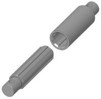
Detail of a spline joint
-
A spline on the end of a manual transmission input shaft
-
Clutch disc with splined hub to mesh with pictured input shaft
-
A drive shaft with a spline in the center and universal joints at the ends to transmit torque and rotation and allow for changes in length
-
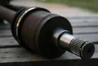
Splines on the CV end of an axle shaft
-
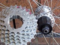
Matching splines of a bicycle cassette and freehub with a master spline visible at the top
Uses
Drive shafts on vehicles and power take-offs use splines to transmit torque and rotation and allow for changes in length. Splines are ubiquitous in aerospace, due to the spline's higher reliability and fatigue life compared to keyed shafts.
Splines are used in several places in bicycles. The crank arm to BB shaft interfaces that are splined include ISIS Drive, Truvativ GXP and Howitzer, Shimano's Octalink and many others, most of which are proprietary. Some cranksets feature modular spiders, where torque is transmitted through splines. Cassettes engage the freehub via a spline that has one groove wider than the others to enforce a fixed orientation. Disc brake mounting interfaces that are splined include Centerlock, by Shimano.
Aircraft engines may have a spline upon which mounts the propeller. There may be a master spline which is wider than the others, so that the propeller may go on at only one orientation, to maintain dynamic balance. This arrangement is commonly found in larger engines, whereas smaller engines typically use a pattern of threaded fasteners instead.
Manufacturing
There are two complementary types of spline, internal and external. External splines may be broached, shaped (for example on a gear shaping machine), milled, hobbed, rolled, ground or extruded. There are fewer methods available for manufacturing internal splines due to accessibility restrictions. Methods include those listed above with the exception of hobbing (no access). Often, with internal splines, the splined portion of the part may not have a through-hole, which precludes use of a pull / push broach or extrusion-type method. Also, if the part is small it may be difficult to fit a milling or grinding tool into the area where the splines are machined.
To prevent stress concentrations the ends of the splines are chamfered (as opposed to an abrupt vertical end). Such stress concentrations are a primary cause of failure in poorly designed splines.[citation needed]
See also
- Coupling
- Hirth joint
- Keyed joint
- Reeding
References
- ↑ "Theory". West Michigan Spline, Inc.. http://westmichiganspline.com/theory/. Retrieved 2010-07-06.
- ↑ 2.0 2.1 2.2 Dan Seger (January 2005). "Inside Splines". Gear Solutions Magazine. http://gearsolutions.com/article/detail/5604/title/inside-splines. Retrieved 2010-07-06. "The externally splined shaft mates with an internal spline that has slots, or spaces, formed in the reverse of the shaft's teeth."
- ↑ Oxford English Dictionary (Second ed.). Oxford University Press. 1989. https://archive.org/details/oxfordenglishdic0006unse. "1966 G. W. MICHALEC Precision Gearing vii. 324 Generally, involute internal and external teeth are mated, but non~involute splines are also suitable. 1979 Industrial Fasteners Handbk. I. 318 There are two basic forms of spline--straight-sided splines which may number 4, 6, 10 or up to 16 splines equally distributed around the circumference of a shaft, and serrated splines which are in the form of adjacent triangular teeth."
Further reading
- Robert Rich Robins (December 2008). "Tooth Engagement Evaluation of Involute Spline Couplings". Brigham Young University. http://scholarsarchive.byu.edu/etd/1834/. Retrieved 2010-07-08.
 |


