Impulse vector
An impulse vector, also known as Kang vector, is a mathematical tool used to graphically design and analyze input shapers that can suppress residual vibration. The impulse vector can be applied to both undamped and underdamped systems, as well as to both positive and negative impulses in a unified manner. The impulse vector makes it easy to obtain impulse time and magnitude of the input shaper graphically.[1] A vector concept for an input shaper was first introduced by W. Singhose[2] for undamped systems with positive impulses. Building on this idea, C.-G. Kang[1] introduced the impulse vector (or Kang vector) to generalize Singhose's idea to undamped and underdamped systems with positive and negative impulses.
Definition

For a vibratory second-order system [math]\displaystyle{ \omega_n^2 /(s^2 + 2 \zeta \omega_n + \omega_n^2 ) }[/math] with undamped natural frequency [math]\displaystyle{ \omega_n }[/math] and damping ratio [math]\displaystyle{ \zeta }[/math], the magnitude [math]\displaystyle{ I_i }[/math] and angle [math]\displaystyle{ \theta_i }[/math] of an impulse vector (or Kang vector) [math]\displaystyle{ \mathbf{I}_i }[/math] corresponding to an impulse function [math]\displaystyle{ A_i \delta (t-t_i) }[/math], [math]\displaystyle{ i = 1,2,...,n }[/math] is defined in a 2-dimensional polar coordinate system as
- [math]\displaystyle{ I_i = A_i e^{\zeta \omega_n t_i } }[/math]
- [math]\displaystyle{ \theta_i = \omega_d t_i }[/math]
where [math]\displaystyle{ A_i }[/math] implies the magnitude of an impulse function, [math]\displaystyle{ t_i }[/math] implies the time location of the impulse function, and [math]\displaystyle{ \omega_d }[/math] implies damped natural frequency [math]\displaystyle{ \omega_n \sqrt{1-\zeta^2} }[/math]. For a positive impulse function with [math]\displaystyle{ A_i \gt 0 }[/math], the initial point of the impulse vector is located at the origin of the polar coordinate system, while for a negative impulse function with [math]\displaystyle{ A_i \lt 0 }[/math], the terminal point of the impulse vector is located at the origin.[1] □
In this definition, the magnitude [math]\displaystyle{ I_i }[/math] is the product of [math]\displaystyle{ A_i }[/math] and a scaling factor for damping during time interval [math]\displaystyle{ t_i }[/math], which represents the magnitude [math]\displaystyle{ A_i }[/math] before being damped; the angle [math]\displaystyle{ \theta_i }[/math] is the product of the impulse time and damped natural frequency. [math]\displaystyle{ \delta(t-t_i) }[/math] represents the Dirac delta function with impulse time at [math]\displaystyle{ t=t_i }[/math].
Note that an impulse function is a purely mathematical quantity, while the impulse vector includes a physical quantity (that is, [math]\displaystyle{ \omega_n }[/math] and [math]\displaystyle{ \zeta }[/math] of a second-order system) as well as a mathematical impulse function. Representing more than two impulse vectors in the same polar coordinate system makes an impulse vector diagram. The impulse vector diagram is a graphical representation of an impulse sequence.

Consider two impulse vectors [math]\displaystyle{ \mathbf{I}_1 }[/math] and [math]\displaystyle{ \mathbf{I}_2 }[/math] in the figure on the right-hand side, in which [math]\displaystyle{ \mathbf{I}_1 }[/math] is an impulse vector with magnitude [math]\displaystyle{ I_1 (\gt 0) }[/math] and angle [math]\displaystyle{ \theta_1 }[/math] corresponding to a positive impulse with [math]\displaystyle{ A_1 \gt 0 }[/math], and [math]\displaystyle{ \mathbf{I}_2 }[/math] is an impulse vector with magnitude [math]\displaystyle{ I_2 = -I_1 }[/math] and angle [math]\displaystyle{ \theta_2 = \pi + \theta_1 }[/math] corresponding to a negative impulse with [math]\displaystyle{ A_2 \lt 0 }[/math]. Since the two time-responses corresponding to [math]\displaystyle{ \mathbf{I}_1 }[/math] and [math]\displaystyle{ \mathbf{I}_2 }[/math] are exactly same after the final impulse time [math]\displaystyle{ t_2 }[/math] as shown in the figure, the two impulse vectors [math]\displaystyle{ \mathbf{I}_1 }[/math] and [math]\displaystyle{ \mathbf{I}_2 }[/math] can be regarded as the same vector for vector addition and subtraction. Impulse vectors satisfy the commutative and associative laws, as well as the distributive law for scalar multiplication.
The magnitude of the impulse vector determines the magnitude of the impulse, and the angle of the impulse vector determines the time location of the impulse. One rotation, [math]\displaystyle{ 2 \pi }[/math] angle, on an impulse vector diagram corresponds to one (damped) period of the corresponding impulse response.
If it is an undamped system ([math]\displaystyle{ \zeta = 0 }[/math]), the magnitude and angle of the impulse vector become [math]\displaystyle{ I_i = A_i }[/math] and [math]\displaystyle{ \theta_i = \omega_n t_i }[/math].
Properties
Property 1: Resultant of two impulse vectors.
The impulse response of a second-order system corresponding to the resultant of two impulse vectors is same as the time response of the system with a two-impulse input corresponding to two impulse vectors after the final impulse time regardless of whether the system is undamped or underdamped. □
Property 2: Zero resultant of impulse vectors.
If the resultant of impulse vectors is zero, the time response of a second-order system for the input of the impulse sequence corresponding to the impulse vectors becomes zero also after the final impulse time regardless of whether the system is undamped or underdamped. □
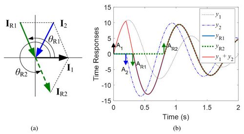
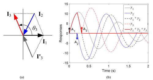
Consider an underdamped second-order system with the transfer function [math]\displaystyle{ 4 \pi^2 / (s^2 + 0.4 \pi s + 4 \pi^2 ) }[/math]. This system has [math]\displaystyle{ \omega_n = 2 \pi }[/math] and [math]\displaystyle{ \zeta = 0.1 }[/math]. For given impulse vectors [math]\displaystyle{ \mathbf{I}_1 }[/math] and [math]\displaystyle{ \mathbf{I}_2 }[/math] as shown in the figure, the resultant can be represented in two ways, [math]\displaystyle{ \mathbf{I}_{R1} }[/math] and [math]\displaystyle{ \mathbf{I}_{R2} }[/math], in which [math]\displaystyle{ \mathbf{I}_{R1} }[/math] corresponds to a negative impulse with [math]\displaystyle{ A_{R1} = I_{R1} / e^{\zeta \omega_n t_{R1}} }[/math] and [math]\displaystyle{ t_{R1} = \theta_{R1} / \omega_d }[/math], and [math]\displaystyle{ \mathbf{I}_{R2} }[/math] corresponds to a positive impulse with [math]\displaystyle{ A_{R2} = I_{R2} / e^{\zeta \omega_n t_{R2}} }[/math] and [math]\displaystyle{ t_{R2} = \theta_{R2} / \omega_d }[/math].
The resultants [math]\displaystyle{ \mathbf{I}_{R1} }[/math], [math]\displaystyle{ \mathbf{I}_{R2} }[/math] can be found as follows.
- [math]\displaystyle{ R_x = I_1 + I_2 \cos \theta_2 , \ \ R_y = I_2 \sin \theta_2 }[/math],
- [math]\displaystyle{ I_{R1} = - \sqrt{R_x^2 + R_y^2},\ \ \theta_{R1} = \pi + \tan^{-1} (R_y / R_x) }[/math]
- [math]\displaystyle{ I_{R2} = \sqrt{R_x^2 + R_y^2},\ \ \theta_{R2} = \tan^{-1} (R_y / R_x) }[/math]
Note that [math]\displaystyle{ - \pi /2 \lt \tan^{-1} (a) \lt \pi /2 }[/math]. The impulse responses [math]\displaystyle{ y_{R1} }[/math] and [math]\displaystyle{ y_{R2} }[/math] corresponding to [math]\displaystyle{ \mathbf{I}_{R1} }[/math] and [math]\displaystyle{ \mathbf{I}_{R2} }[/math] are exactly same with [math]\displaystyle{ y_1 + y_2 }[/math] after each impulse time location as shown in green lines of the figure (b).
Now, place an impulse vector [math]\displaystyle{ \mathbf{I}_3 }[/math] on the impulse vector diagram to cancel the resultant [math]\displaystyle{ \mathbf{I}_1 + \mathbf{I}_2 }[/math] as shown in the figure. The impulse vector [math]\displaystyle{ \mathbf{I}_3 }[/math] is given by
- [math]\displaystyle{ I_3 = \sqrt{R_x^2 + R_y^2},\ \ \theta_3 = \pi + \tan^{-1}(R_y /R_x ) }[/math].
When the impulse sequence corresponding to three impulse vectors [math]\displaystyle{ \mathbf{I}_1, \mathbf{I}_2 }[/math] and [math]\displaystyle{ \mathbf{I}_3 }[/math] is applied to a second-order system as an input, the resulting time response causes no residual vibration after the final impulse time [math]\displaystyle{ t_3 }[/math] as shown in the red line of the bottom figure (b). Of course, another canceling vector [math]\displaystyle{ \mathbf{I}^'_3 }[/math] can exist, which is the impulse vector with the same magnitude as [math]\displaystyle{ \mathbf{I}_3 }[/math] but with an opposite arrow direction. However, this canceling vector has a longer impulse time that can be as much as a half period compared to [math]\displaystyle{ \mathbf{I}_3 }[/math].
Applications: Design of input shapers using impulse vectors
ZVDn shaper
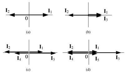
Using impulse vectors, we can redesign[1] known input shapers [3] such as zero vibration (ZV), zero vibration and derivative (ZVD), and ZVDn shapers. The ZV shaper is composed of two impulse vectors, in which the first impulse vector is located at 0°, and the second impulse vector with the same magnitude is located at 180° for [math]\displaystyle{ \mathbf{I}_1 + \mathbf{I}_2 = \mathbf{0} }[/math]. Then from the impulse vector diagram of the ZV shaper on the right-hand side,
- [math]\displaystyle{ \theta_1 = 0, \ \ \theta_2 = \pi }[/math]
- [math]\displaystyle{ I_1 = I_2 = I }[/math].
Therefore, [math]\displaystyle{ t_1 = 0, \ \ t_2 = \pi/ \omega_d }[/math].
Since [math]\displaystyle{ A_1 + A_2 = 1 }[/math] (normalization constraint) must be hold, and [math]\displaystyle{ A_1 = I_1, \ \ A_2 = I_2 / e^{\zeta \omega_n t_2} }[/math],
- [math]\displaystyle{ I_1 + \frac {I_2}{e^{\zeta \omega_n t_2 }} = I + \frac {I}{K} = 1, \quad K=e^{\zeta \pi / \sqrt {1-\zeta^2 }} }[/math].
Therefoere, [math]\displaystyle{ I = K/(K+1) }[/math].
Thus, the ZV shaper [math]\displaystyle{ A_1 \delta (t) + A_2 \delta (t-t_2) }[/math] is given by
- [math]\displaystyle{ \begin{bmatrix} t_i \\ A_i \end{bmatrix} = \begin{bmatrix} 0, & \pi / \omega_d \\ K/(K+1), & 1/(K+1) \end{bmatrix} }[/math].
[math]\displaystyle{ \quad }[/math]
The ZVD shaper is composed of three impulse vectors, in which the first impulse vector is located at 0 rad, the second vector at [math]\displaystyle{ \pi }[/math] rad, and the third vector at [math]\displaystyle{ 2 \pi }[/math] rad, and the magnitude ratio is [math]\displaystyle{ I_1 : I_2 : I_3 = 1:2:1 }[/math]. Then [math]\displaystyle{ \mathbf{I}_1 + \mathbf{I}_2 + \mathbf{I}_3 = \mathbf{0} }[/math]. From the impulse vector diagram,
- [math]\displaystyle{ \theta_1 = 0, \ \ \theta_2 = \pi , \ \ \theta_3 = 2 \pi }[/math].
Therefore, [math]\displaystyle{ t_1 = 0, \ t_2 = \pi/ \omega_d , \ t_3 = 2 \pi/ \omega_d }[/math].
Also from the impulse vector diagram,
- [math]\displaystyle{ I_1 = I_3 = I, \ \ I_2 = 2I }[/math].
Since [math]\displaystyle{ A_1 + A_2 + A_3 = 1 }[/math] must be hold,
- [math]\displaystyle{ I_1 + \frac {I_2}{e^{\zeta \omega_n t_3}} + \frac {I_3}{e^{\zeta \omega_n t_3}} = I+ \frac{2I}{K}+ \frac{I}{K^2} = 1, \ \ K=e^{\zeta \pi / \sqrt {1-\zeta^2 }} }[/math].
Therefore, [math]\displaystyle{ I=K^2 /(K+1)^2 }[/math].
Thus, the ZVD shaper [math]\displaystyle{ A_1 \delta (t) + A_2 \delta (t-t_2) + A_3 \delta (t- t_3 ) }[/math] is given by
- [math]\displaystyle{ \begin{bmatrix} t_i \\ A_i \end{bmatrix} = \begin{bmatrix} 0, & \pi / \omega_d, & 2 \pi / \omega_d\\ K^2/(K+1)^2, & 2K/(K+1)^2, & 1/(K+1)^2 \end{bmatrix} }[/math].
[math]\displaystyle{ \quad }[/math]
The ZVD2 shaper is composed of four impulse vectors, in which the first impulse vector is located at 0 rad, the second vector at [math]\displaystyle{ \pi }[/math] rad, the third vector at [math]\displaystyle{ 2 \pi }[/math] rad, and the fourth vector at [math]\displaystyle{ 3 \pi }[/math] rad, and the magnitude ratio is [math]\displaystyle{ I_1 : I_2 : I_3 : I_4 = 1:3:3:1 }[/math]. Then [math]\displaystyle{ \mathbf{I}_1 + \mathbf{I}_2 + \mathbf{I}_3 + \mathbf{I}_4 = \mathbf{0} }[/math]. From the impulse vector diagram,
- [math]\displaystyle{ \theta_1 = 0, \ \ \theta_2 = \pi , \ \ \theta_3 = 2 \pi , \ \ \theta_4 = 3 \pi }[/math].
Therefore, [math]\displaystyle{ t_1 = 0, \ \ t_2 = \pi / \omega_d , \ \ t_3 = 2 \pi / \omega_d , \ \ t_4 = 3 \pi / \omega_d }[/math].
Also, from the impulse vector diagram,
- [math]\displaystyle{ I_1 = I_4 = I, \ \ I_2 = I_3 = 3I }[/math].
Since [math]\displaystyle{ A_1 + A_2 + A_3 + A_4 = 1 }[/math] must be hold,
- [math]\displaystyle{ I_1 + \frac {I_2}{e^{\zeta \omega_n t_2}} + \frac {I_3}{e^{\zeta \omega_n t_3}} + \frac {I_4}{e^{\zeta \omega_n t_4}} = I + \frac {3I}{K} + \frac {3I}{K^2} + \frac {I}{K^3} = 1, \ \ \ K=e^{\zeta \pi / \sqrt {1-\zeta^2 }} }[/math].
Therefore, [math]\displaystyle{ I = K^3 / (K+1)^3 }[/math].
Thus, the ZVD2 shaper [math]\displaystyle{ A_1 \delta (t) + A_2 \delta (t-t_2) + A_3 \delta (t-t_3) + A_4 \delta (t-t_4) }[/math] is given by
- [math]\displaystyle{ \begin{bmatrix} t_i \\ A_i \end{bmatrix} = \begin{bmatrix} 0, & \pi / \omega_d, & 2 \pi / \omega_d, & 3 \pi / \omega_d \\ K^3/(K+1)^3, & 3K^2/(K+1)^3, & 3K/(K+1)^3, & 1/(K+1)^3 \end{bmatrix} }[/math].
[math]\displaystyle{ \quad }[/math]
Similarly, the ZVD3 shaper with five impulse vectors can be obtained, in which the first vector is located at 0 rad, the second vector at [math]\displaystyle{ \pi }[/math] rad, third vector at [math]\displaystyle{ 2 \pi }[/math] rad, the fourth vector at [math]\displaystyle{ 3 \pi }[/math] rad, and the fifth vector at [math]\displaystyle{ 4 \pi }[/math] rad, and the magnitude ratio is [math]\displaystyle{ I_1 : I_2 : I_3 : I_4 : I_5 = 1:4:6:4:1 }[/math]. In general, for the ZVDn shaper, i-th impulse vector is located at [math]\displaystyle{ (i-1) \pi }[/math] rad, and the magnitude ratio is [math]\displaystyle{ I_1 : I_2 : I_3 : \cdots : I_{n+2} = \tbinom{n+1}{0} : \tbinom{n+1}{1} : \tbinom{n+1}{2} : \cdots : \tbinom{n+1}{n+1} }[/math] where [math]\displaystyle{ \tbinom{m}{k} }[/math] implies a mathematical combination.
ETM shaper
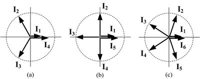
Now, consider equal shaping-time and magnitudes (ETM) shapers,[1] with the same magnitude of impulse vectors and with the same angle between impulse vectors. The ETMn shaper satisfies the conditions
- [math]\displaystyle{ \theta_1 = 0, \ \ \theta_2 = \frac{2 \pi}{n-1}, \cdots , \theta_{n-1} = \frac{(n-2)2 \pi}{n-1}\ \ }[/math]
- [math]\displaystyle{ I_2 = I_3 = \cdots = I_{n-1} = I_1 + I_n , \ \ I_n = mI_1 \ (m\gt 0) }[/math]
- [math]\displaystyle{ \sum_{i=1}^{n} A_i = 1 }[/math].
Thus, the resultant of the impulse vectors of the ETMn shaper becomes always zero for all [math]\displaystyle{ n \ge 2 }[/math]. One merit of the ETMn shaper is that, unlike the ZVDn or extra insensitive (EI) shapers,[4] the shaping time is always one (damped) period of the time response even if n increases. The ETM4 shaper with four impulse vectors is obtained from the above conditions together with impulse vector definitions as
- [math]\displaystyle{ \begin{bmatrix} t_i \\ A_i \end{bmatrix} = \begin{bmatrix} 0, & (2 \pi /3) / \omega_d, & (4 \pi /3) / \omega_d, & 2 \pi / \omega_d \\ I/(1+m), & I/K^{2/3}, & I/K^{4/3}, & mI/ [(1+m)K^2] \end{bmatrix} }[/math].
- [math]\displaystyle{ I=\frac{(1+m)K^2}{K^2 + (1+m)(K^{4/3} + K^{2/3})+m} , \quad K=e^{\zeta \pi / \sqrt{1-\zeta^2}} }[/math].
The ETM5 shaper with five impulse vectors is obtained similarly as
- [math]\displaystyle{ \begin{bmatrix} t_i \\ A_i \end{bmatrix} = \begin{bmatrix} 0, & 0.5 \pi / \omega_d, & \pi / \omega_d, & 1.5 \pi / \omega_d , & 2 \pi / \omega_d\\ I/(1+m), & I/K^{1/2}, & I/K, & I/K^{3/2}, & mI/ [(1+m)K^2] \end{bmatrix} }[/math].
- [math]\displaystyle{ I=\frac{(1+m)K^2}{K^2 + (1+m)(K^{3/2} + K + K^{1/2})+m} ,\quad K=e^{\zeta \pi / \sqrt{1-\zeta^2}} }[/math].
In the same way, the ETMn shaper with [math]\displaystyle{ n \ge 6 }[/math] can be obtained easily. In general, ETM shapers are less sensitive to modeling errors than ZVDn shapers in a large positive error range. Note that the ZVD shaper is an ETM3 shaper with [math]\displaystyle{ m=1 }[/math].
NMe shaper
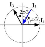
Moreover, impulse vectors can be applied to design input shapers with negative impulses. Consider a negative equal-magnitude (NMe) shaper,[1] in which the magnitudes of three impulse vectors are [math]\displaystyle{ I_1 = I (\gt 0), \ I_2 = -I,\ I_3 = I }[/math], and the angles are [math]\displaystyle{ \theta_1 = 0, \ \theta_2 = \pi /3,\ \theta_3 = 2 \pi /3 }[/math]. Then the resultant of three impulse vectors becomes zero, and thus the residual vibration is suppressed. Impulse time [math]\displaystyle{ t_2, t_3 }[/math] of the NMe shaper are obtained as [math]\displaystyle{ t_2 = (\pi /3)/ \omega_d, \ t_3 = (2 \pi /3)/ \omega_d }[/math], and impulse magnitudes are obtained easily by solving the simultaneous equations
- [math]\displaystyle{ A_1 = I, A_2 = -I/e^{\zeta \omega_n t_2}, \ \ A_3 = I/e^{\zeta \omega_n t_3} }[/math]
- [math]\displaystyle{ A_1 + A_2 + A_3 = 1 }[/math].
The resulting NMe shaper [math]\displaystyle{ A_1 \delta (t) + A_2 \delta (t-t_2) + A_3 \delta (t-t_3) }[/math] is
- [math]\displaystyle{ \begin{bmatrix} t_i \\ A_i \end{bmatrix} = \begin{bmatrix} 0, & ( \pi /3) / \omega_d, & (2 \pi /3)/ \omega_d \\ I, & -I/K^{1/3}, & I/K^{2/3} \end{bmatrix} }[/math].
- [math]\displaystyle{ I = K/(K-K^{2/3} + K^{1/3}), \ \ \ K=e^{\zeta \pi / \sqrt{1- \zeta^2}} }[/math].
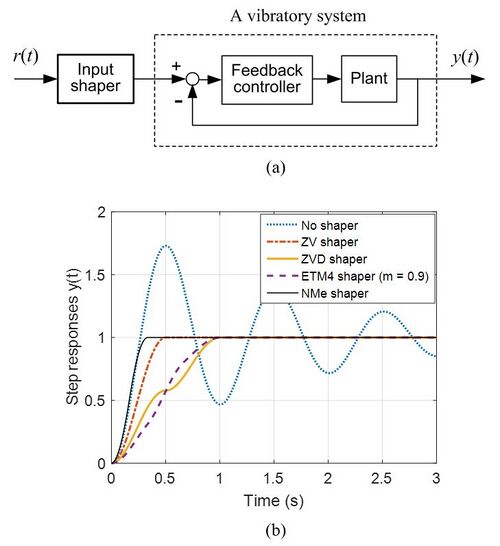
The NMe shaper has faster rise time than the ZVD shaper, but it is more sensitive to modeling error than the ZVD shaper. Note that the NMe shaper is the same with the UM shaper[5] if the system is undamped ([math]\displaystyle{ \zeta = 0 }[/math]).
Figure (a) in the right side shows a typical block diagram of an input-shaping control system, and figure (b) shows residual vibration suppressions in unit-step responses by ZV, ZVD, ETM4 and NMe shapers.
Refer to the reference[1] for sensitivity curves of the above input shapers, which represent the robustness to modeling errors in [math]\displaystyle{ \omega_n }[/math] and [math]\displaystyle{ \zeta }[/math].
References
- ↑ 1.0 1.1 1.2 1.3 1.4 1.5 1.6 Kang, Chul-Goo (August 2019). "Impulse vectors for input shaping control: A mathematical tool to design and analyze input shapers". IEEE Control Systems Magazine 39 (4): 40–55. doi:10.1109/MCS.2019.2913610. http://home.konkuk.ac.kr/~cgkang/ImpulseVectorsForInputShapingControl.pdf.
- ↑ Singhose, W.; Seering, W.; Singer, N. (1994). "Residual vibration reduction using vector diagrams to generate shaped inputs". Journal of Mechanical Design 116 (2): 654–659. doi:10.1115/1.2919428.
- ↑ Singhose, W. (2009). "Command shaping for flexible systems: A review of the first 50 years". International Journal of Precision Engineering and Manufacturing 10 (4): 153–168. doi:10.1007/s12541-009-0084-2.
- ↑ Singhose, W.; Derezinski, S.; Singer, N. (1996). "Extra-insensitive input shapers for controlling flexible spacecraft". Journal of Guidance, Control and Dynamics 19 (2): 385–391. doi:10.2514/3.21630. Bibcode: 1996JGCD...19..385S.
- ↑ Singhose, W. E.; Seering, W. P.; Singer, N. C. (1997). "Time-optimal negative input shapers". Journal of Dynamic Systems, Measurement, and Control 119 (2): 198–205. doi:10.1115/1.2801233.
 |
