Lifting scheme

The lifting scheme is a technique for both designing wavelets and performing the discrete wavelet transform (DWT). In an implementation, it is often worthwhile to merge these steps and design the wavelet filters while performing the wavelet transform. This is then called the second-generation wavelet transform. The technique was introduced by Wim Sweldens.[1]
The lifting scheme factorizes any discrete wavelet transform with finite filters into a series of elementary convolution operators, so-called lifting steps, which reduces the number of arithmetic operations by nearly a factor two. Treatment of signal boundaries is also simplified.[2]
The discrete wavelet transform applies several filters separately to the same signal. In contrast to that, for the lifting scheme, the signal is divided like a zipper. Then a series of convolution–accumulate operations across the divided signals is applied.
Basics
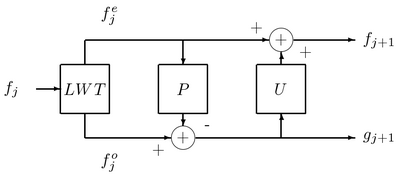
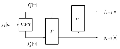
The simplest version of a forward wavelet transform expressed in the lifting scheme is shown in the figure above. means predict step, which will be considered in isolation. The predict step calculates the wavelet function in the wavelet transform. This is a high-pass filter. The update step calculates the scaling function, which results in a smoother version of the data.
As mentioned above, the lifting scheme is an alternative technique for performing the DWT using biorthogonal wavelets. In order to perform the DWT using the lifting scheme, the corresponding lifting and scaling steps must be derived from the biorthogonal wavelets. The analysis filters () of the particular wavelet are first written in polyphase matrix
where .
The polyphase matrix is a 2 × 2 matrix containing the analysis low-pass and high-pass filters, each split up into their even and odd polynomial coefficients and normalized. From here the matrix is factored into a series of 2 × 2 upper- and lower-triangular matrices, each with diagonal entries equal to 1. The upper-triangular matrices contain the coefficients for the predict steps, and the lower-triangular matrices contain the coefficients for the update steps. A matrix consisting of all zeros with the exception of the diagonal values may be extracted to derive the scaling-step coefficients. The polyphase matrix is factored into the form
where is the coefficient for the predict step, and is the coefficient for the update step.
An example of a more complicated extraction having multiple predict and update steps, as well as scaling steps, is shown below; is the coefficient for the first predict step, is the coefficient for the first update step, is the coefficient for the second predict step, is the coefficient for the second update step, is the odd-sample scaling coefficient, and is the even-sample scaling coefficient:
According to matrix theory, any matrix having polynomial entries and a determinant of 1 can be factored as described above. Therefore, every wavelet transform with finite filters can be decomposed into a series of lifting and scaling steps. Daubechies and Sweldens discuss lifting-step extraction in further detail.[3]
CDF 9/7 filter
To perform the CDF 9/7 transform, a total of four lifting steps are required: two predict and two update steps. The lifting factorization leads to the following sequence of filtering steps.[3]
Properties
Perfect reconstruction
Every transform by the lifting scheme can be inverted. Every perfect-reconstruction filter bank can be decomposed into lifting steps by the Euclidean algorithm. That is, "lifting-decomposable filter bank" and "perfect-reconstruction filter bank" denotes the same. Every two perfect-reconstruction filter banks can be transformed into each other by a sequence of lifting steps. For a better understanding, if and are polyphase matrices with the same determinant, then the lifting sequence from to is the same as the one from the lazy polyphase matrix to .
Speedup
Speedup is by a factor of two. This is only possible because lifting is restricted to perfect-reconstruction filter banks. That is, lifting somehow squeezes out redundancies caused by perfect reconstruction.
The transformation can be performed immediately in the memory of the input data (in place, in situ) with only constant memory overhead.
Non-linearities
The convolution operations can be replaced by any other operation. For perfect reconstruction only the invertibility of the addition operation is relevant. This way rounding errors in convolution can be tolerated and bit-exact reconstruction is possible. However, the numeric stability may be reduced by the non-linearities. This must be respected if the transformed signal is processed like in lossy compression. Although every reconstructable filter bank can be expressed in terms of lifting steps, a general description of the lifting steps is not obvious from a description of a wavelet family. However, for instance, for simple cases of the Cohen–Daubechies–Feauveau wavelet, there is an explicit formula for their lifting steps.
Increasing vanishing moments, stability, and regularity
A lifting modifies biorthogonal filters in order to increase the number of vanishing moments of the resulting biorthogonal wavelets, and hopefully their stability and regularity. Increasing the number of vanishing moments decreases the amplitude of wavelet coefficients in regions where the signal is regular, which produces a more sparse representation. However, increasing the number of vanishing moments with a lifting also increases the wavelet support, which is an adverse effect that increases the number of large coefficients produced by isolated singularities. Each lifting step maintains the filter biorthogonality but provides no control on the Riesz bounds and thus on the stability of the resulting wavelet biorthogonal basis. When a basis is orthogonal then the dual basis is equal to the original basis. Having a dual basis that is similar to the original basis is, therefore, an indication of stability. As a result, stability is generally improved when dual wavelets have as much vanishing moments as original wavelets and a support of similar size. This is why a lifting procedure also increases the number of vanishing moments of dual wavelets. It can also improve the regularity of the dual wavelet. A lifting design is computed by adjusting the number of vanishing moments. The stability and regularity of the resulting biorthogonal wavelets are measured a posteriori, hoping for the best. This is the main weakness of this wavelet design procedure.
Generalized lifting

The generalized lifting scheme was developed by Joel Solé and Philippe Salembier and published in Solé's PhD dissertation.[4] It is based on the classical lifting scheme and generalizes it by breaking out a restriction hidden in the scheme structure. The classical lifting scheme has three kinds of operations:
- A lazy wavelet transform splits signal in two new signals: the odd-samples signal denoted by and the even-samples signal denoted by .
- A prediction step computes a prediction for the odd samples, based on the even samples (or vice versa). This prediction is subtracted from the odd samples, creating an error signal .
- An update step recalibrates the low-frequency branch with some of the energy removed during subsampling. In the case of classical lifting, this is used in order to "prepare" the signal for the next prediction step. It uses the predicted odd samples to prepare the even ones (or vice versa). This update is subtracted from the even samples, producing the signal denoted by .
The scheme is invertible due to its structure. In the receiver, the update step is computed first with its result added back to the even samples, and then it is possible to compute exactly the same prediction to add to the odd samples. In order to recover the original signal, the lazy wavelet transform has to be inverted. Generalized lifting scheme has the same three kinds of operations. However, this scheme avoids the addition-subtraction restriction that offered classical lifting, which has some consequences. For example, the design of all steps must guarantee the scheme invertibility (not guaranteed if the addition-subtraction restriction is avoided).
Definition

Generalized lifting scheme is a dyadic transform that follows these rules:
- Deinterleaves the input into a stream of even-numbered samples and another stream of odd-numbered samples. This is sometimes referred to as a lazy wavelet transform.
- Computes a prediction mapping. This step tries to predict odd samples taking into account the even ones (or vice versa). There is a mapping from the space of the samples in to the space of the samples in . In this case the samples (from ) chosen to be the reference for are called the context. It could be expressed as
- Computes an update mapping. This step tries to update the even samples taking into account the odd predicted samples. It would be a kind of preparation for the next prediction step, if any. It could be expressed as
Obviously, these mappings cannot be any functions. In order to guarantee the invertibility of the scheme itself, all mappings involved in the transform must be invertible. In case that mappings arise and arrive on finite sets (discrete bounded value signals), this condition is equivalent to saying that mappings are injective (one-to-one). Moreover, if a mapping goes from one set to a set of the same cardinality, it should be bijective.
In the generalized lifting scheme the addition/subtraction restriction is avoided by including this step in the mapping. In this way the classical lifting scheme is generalized.
Design
Some designs have been developed for the prediction-step mapping. The update-step design has not been considered as thoroughly, because it remains to be answered how exactly the update step is useful. The main application of this technique is image compression. There some interesting references such as,[5][6][7] and.[8]
Applications
- Wavelet transforms that map integers to integers
- Fourier transform with bit-exact reconstruction[9]
- Construction of wavelets with a required number of smoothness factors and vanishing moments
- Construction of wavelets matched to a given pattern[10]
- Implementation of the discrete wavelet transform in JPEG 2000
- Data-driven transforms, e.g., edge-avoiding wavelets[11]
- Wavelet transforms on non-separable lattices, e.g., red-black wavelets on the quincunx lattice[12]
See also
- The Feistel scheme in cryptology uses much the same idea of dividing data and alternating function application with addition. Both in the Feistel scheme and the lifting scheme this is used for symmetric en- and decoding.
References
- ↑ Sweldens, Wim (1997). "The Lifting Scheme: A Construction of Second Generation Wavelets". Journal on Mathematical Analysis 29 (2): 511–546. doi:10.1137/S0036141095289051. https://cm-bell-labs.github.io/who/wim/papers/lift2.pdf.
- ↑ Mallat, Stéphane (2009). A Wavelet Tour of Signal Processing. Academic Press. ISBN 978-0-12-374370-1. https://wavelet-tour.github.io/.
- ↑ 3.0 3.1 Daubechies, Ingrid; Sweldens, Wim (1998). "Factoring Wavelet Transforms into Lifting Steps". Journal of Fourier Analysis and Applications 4 (3): 247–269. doi:10.1007/BF02476026. https://9p.io/who/wim/papers/factor/factor.pdf.
- ↑ Ph.D. dissertation: Optimization and Generalization of Lifting Schemes: Application to Lossless Image Compression.
- ↑ Rolon, J. C.; Salembier, P. (Nov 7–9, 2007). "Generalized Lifting for Sparse Image Representation and Coding". https://www.researchgate.net/publication/228347925.
- ↑ Rolon, J. C.; Salembier, P.; Alameda, X. (Oct 12–15, 2008). "Image Compression with Generalized Lifting and partial knowledge of the signal pdf". https://www.academia.edu/download/40211740/cRolon08.pdf.[|permanent dead link|dead link}}]
- ↑ Rolon, J. C.; Ortega, A.; Salembier, P.. "Modeling of Contours in Wavelet Domain for Generalized Lifting Image Compression". https://upcommons.upc.edu/bitstream/handle/2117/9008/modelingcontours.pdf.
- ↑ Rolon, J. C.; Mendonça, E.; Salembier, P.. "Generalized Lifting With Adaptive Local pdf estimation for Image Coding". https://upcommons.upc.edu/bitstream/handle/2117/8835/GeneralizedLifting.pdf.
- ↑ Oraintara, Soontorn; Chen, Ying-Jui; Nguyen, Truong Q. (2002). "Integer Fast Fourier Transform". IEEE Transactions on Signal Processing 50 (3): 607–618. doi:10.1109/78.984749. Bibcode: 2002ITSP...50..607O. http://www-ee.uta.edu/msp/pub/Journaintfft.pdf.
- ↑ Thielemann, Henning (2004). "Optimally matched wavelets". Proceedings in Applied Mathematics and Mechanics 4: 586–587. doi:10.1002/pamm.200410274.
- ↑ Fattal, Raanan (2009). "Edge-Avoiding Wavelets and their Applications". ACM Transactions on Graphics 28 (3): 1–10. doi:10.1145/1531326.1531328. http://www.cs.huji.ac.il/~raananf/projects/eaw/.
- ↑ Uytterhoeven, Geert; Bultheel, Adhemar (1998). "The Red-Black Wavelet Transform". Signal Processing Symposium (IEEE Benelux). pp. 191–194. http://nalag.cs.kuleuven.be/papers/ade/redblack/.
External links
- Lifting Scheme – brief description of the factoring algorithm
- Introduction to The Lifting Scheme
- The Fast Lifting Wavelet Transform
 |
