PDP-14
The PDP-14 was a specialized computer from Digital Equipment Corporation’s Industrial Products Group designed to replace industrial level relay controls for machinery and machine tools that performed repetitive tasks. It was specifically designed to function in the harsh electrical environment encountered in facilities where electric motors, solenoids and arc welders were present, a significant adversity for normal computer electronics. The PDP-14 was specifically designed to be the first level of factory automation, functioning as a programmable logic controller (PLC), through its ability to communicate with a standard DEC PDP-8 minicomputer.[1][2]
The first unit was delivered in June 1969 and used to control a gear grinding machine.[3] Its design as a "programmable machine controller" was patented in 1973.[4]
The PDP-14 was designed to process Boolean equations, usually expressed as “ladder diagrams” and as such had a programmable read-only program (PROM) memory. Programs were developed using a PDP-8 then tested using a direct connection to the PDP-14. The PDP-14 was put into a check out mode where instructions were provided by the PDP-8. Following checkout, the PDP-8 provided the instructions to be put into the PROM.
Later versions (for example, the PDP-14/30, whose instruction set was not binary compatible)[5] are based on PDP-8 physical packaging technology. There also was a PDP-14/35[6] and a lower cost/reduced I/O capability PDP-14/L.
Hardware
The 12-bit PDP-14 could hold a maximum of 4K words for instructions. The system's configuration included a control unit and a number of external boxes:[5]
- I-boxes (BX14) were for discrete inputs from the controlled system. Up to 256 input sources could be addressed.
- O-boxes (BY14) could control up to 255 actuators in the controlled system.
- A-boxes could be filled with timer modules for controlling time-driven events or retentive storage modules which were not cleared with power loss. A-boxes occupied the output address space along with the O-boxes.
- S-boxes were essentially the same as the O-boxes, but there was no real output device. This enabled storing intermediate results. S-boxes also used the shared output address space.
Hence the combined usable output address space of the O-boxes, A-boxes and S-boxes was 255 or fewer.
Registers
The PDP-14 has seven 12-bit registers:[5]
IRPC1&PC2MBSPAREINPUTandOUTPUT.
Instructions
Among the PDP-14 instructions were:[5]
TRR– to move data between some (but not all) of the registers – TRansfer Register (contents).
PC1andSPAREhave increment and decrement capabilities, permittingTRRto modify the value loaded into the register.
JMS– JuMp to Subroutine – at the address specified in the following 12-bit word, saving the return address inPC2JMR– JuMp to RETURN from a subroutine, jumps to location saved inPC2.[5] In effect, JMR is aTRRin whichPC2is transferred toPC1.
SKP– SKiP – is aTRRin whichPC1is incremented by 1.
There were also TEST instructions (Test if something is ON or OFF) and SET instructions (SYN – Set "Y" oN, SYF – Set "Y" ofF).
Software
The original PDP-14 required that programming be done by DEC.[7]
Subsequently,[7] software development for the PDP-14 was done on another system, the PDP-8. A PDP-8 program named SIM-14 allowed for simulating the PDP-14.
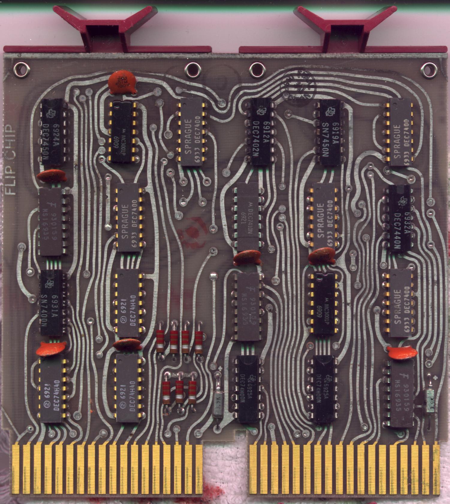
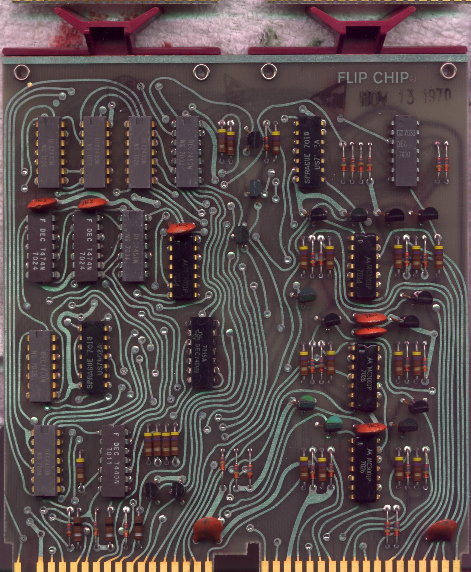
Photos
See also
References
- ↑ Bell, C. Gordon; Mudge, J. Craig; McNamara, John E. (2014-05-12) (in en). Computer Engineering: A DEC View of Hardware Systems Design. Digital Press. ISBN 978-1-4832-2110-6. https://books.google.com/books?id=SDOoBQAAQBAJ&dq=%22pdp-14%22+computer+-wikipedia&pg=PA208.
- ↑ (in en) PDP 8/e, PDP 8/m & PDP 8/f Small Computer Handbook. Digital Equipment Corporation. 1973. p. 1-46. http://bitsavers.org/pdf/dec/pdp8/handbooks/Small_Computer_Handbook_1973.pdf.
- ↑ Ball, Ken (2015-08-02). "The Dawn of the Programmable Logic Controller (PLC)" (in en). https://www.automation.com/en-us/articles/2015-2/the-dawn-of-the-programmable-logic-controller-plc.
- ↑ , A.; A. Devault & R. Doane et al."Programmable machine controller" patent US3753243A, issued 1973-08-14
- ↑ 5.0 5.1 5.2 5.3 5.4 "DEC PDP-14 Industrial Controller". http://www.chdickman.com/pdp14.
- ↑ Nineteen Fifty-Seven To The Present. Digital Equipment Corporation. 1975. http://s3data.computerhistory.org/pdp-1/dec.digital_1957_to_the_present_(1978).1957-1978.102630349.pdf.
- ↑ 7.0 7.1 Randall Brodzik (August 27, 2014). "Inside the competition for the first PLC". http://www.controleng.com/single-article/inside-the-competition-for-the-first-plc/2455e5713e5c2cf400fdccc5f35923be.html.
External links
 |  |
