Physics:Ballistic pendulum
A ballistic pendulum is a device for measuring a bullet's momentum, from which it is possible to calculate the velocity and kinetic energy. Ballistic pendulums have been largely rendered obsolete by modern chronographs, which allow direct measurement of the projectile velocity.
Although the ballistic pendulum is considered obsolete, it remained in use for a significant length of time and led to great advances in the science of ballistics. The ballistic pendulum is still found in physics classrooms today, because of its simplicity and usefulness in demonstrating properties of momentum and energy. Unlike other methods of measuring the speed of a bullet, the basic calculations for a ballistic pendulum do not require any measurement of time, but rely only on measures of mass and distance.[1]
In addition its primary uses of measuring the velocity of a projectile or the recoil of a gun, the ballistic pendulum can be used to measure any transfer of momentum. For example, a ballistic pendulum was used by physicist C. V. Boys to measure the elasticity of golf balls,[2] and by physicist Peter Guthrie Tait to measure the effect that spin had on the distance a golf ball traveled.[3][4]
History
The ballistic pendulum was invented in 1742 by English mathematician Benjamin Robins (1707–1751), and published in his book New Principles of Gunnery, which revolutionized the science of ballistics, as it provided the first way to accurately measure the velocity of a bullet.[2][5]
Robins used the ballistic pendulum to measure projectile velocity in two ways. The first was to attach the gun to the pendulum, and measure the recoil. Since the momentum of the gun is equal to the momentum of the ejecta, and since the projectile was (in those experiments) the large majority of the mass of the ejecta, the velocity of the bullet could be approximated. The second, and more accurate method, was to directly measure the bullet momentum by firing it into the pendulum. Robins experimented with musket balls of around one ounce in mass (28 g), while other contemporaries used his methods with cannon shot of one to three pounds (0.5 to 1.4 kg).[6]
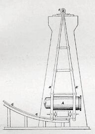
Robins' original work used a heavy iron pendulum, faced with wood, to catch the bullet. Modern reproductions, used as demonstrations in physics classes, generally use a heavy weight suspended by a very fine, lightweight arm, and ignore the mass of the pendulum's arm. Robins' heavy iron pendulum did not allow this, and Robins' mathematical approach was slightly more complex. He used the period of oscillation and mass of the pendulum (both measured with the bullet included) to calculate the rotational inertia of the pendulum, which was then used in the calculations. Robins also used a length of ribbon, loosely gripped in a clamp, to measure the travel of the pendulum. The pendulum would draw out a length of ribbon equal to the chord of pendulum's travel.[7]
The first system to supplant ballistic pendulums with direct measures of projectile speed was invented in 1808, during the Napoleonic Wars and used a rapidly rotating shaft of known speed with two paper disks on it; the bullet was fired through the disks, parallel to the shaft, and the angular difference in the points of impact provided an elapsed time over the distance between the disks. A direct electromechanical clockwork measure appeared in 1848, with a spring-driven clock started and stopped by electromagnets, whose current was interrupted by the bullet passing through two meshes of fine wires, again providing the time to traverse the given distance.[2]
Mathematical derivations
Most physics textbooks provide a simplified method of calculation of the bullet's velocity that uses the mass of the bullet and pendulum and the height of the pendulum's travel to calculate the amount of energy and momentum in the pendulum and bullet system. Robins' calculations were significantly more involved, and used a measure of the period of oscillation to determine the rotational inertia of the system.
Simple derivation
We begin with the motion of the bullet-pendulum system from the instant the pendulum is struck by the bullet.
Given [math]\displaystyle{ g }[/math], the acceleration due to gravity, and [math]\displaystyle{ h }[/math], the final height of the pendulum, it is possible to calculate the initial velocity of the bullet-pendulum system using conservation of mechanical energy (kinetic energy + potential energy). Let this initial velocity be denoted by [math]\displaystyle{ v_1 }[/math]. Suppose the masses of the bullet and pendulum are [math]\displaystyle{ m_b }[/math] and [math]\displaystyle{ m_p }[/math] respectively.
The initial kinetic energy of the system [math]\displaystyle{ K_{initial} =\begin{matrix}\frac{1}{2}\end{matrix}(m_{b}+m_{p})\cdot v_1^2 }[/math]
Taking the initial height of the pendulum as the potential energy reference [math]\displaystyle{ (U_{initial}=0) }[/math], the final potential energy when the bullet-pendulum system comes to a stop [math]\displaystyle{ (K_{final} = 0) }[/math] is given by [math]\displaystyle{ U_{final} = (m_{b}+m_{p})\cdot g\cdot h }[/math]
So, by the conservation of mechanical energy, we have:[8]
- [math]\displaystyle{ K_{initial} = U_{final} \, }[/math]
- [math]\displaystyle{ \begin{matrix}\frac{1}{2}\end{matrix} (m_{b}+m_{p})\cdot v_1^2 = (m_{b}+m_{p})\cdot g\cdot h }[/math]
- Solve for velocity to obtain: [math]\displaystyle{ v_1 = \sqrt{2\cdot g\cdot h} }[/math]
We can now use momentum conservation for the bullet-pendulum system to get the speed of the bullet, [math]\displaystyle{ v_0 }[/math], before it struck the pendulum. Equating the momentum of the bullet before it impacts the pendulum to that of the bullet-pendulum system as soon as the bullet strikes the pendulum (and using [math]\displaystyle{ v_1 = \sqrt{2\cdot g\cdot h} }[/math] from above), we get:
- [math]\displaystyle{ m_\textrm{b}\cdot v_0 = (m_\textrm{b}+m_\textrm{p}) \cdot \sqrt{2\cdot g\cdot h} }[/math]
Solving for [math]\displaystyle{ v_0 }[/math]:
- [math]\displaystyle{ v_0 = \frac{(m_\textrm{b}+m_\textrm{p}) \cdot \sqrt{2\cdot g\cdot h}}{m_\textrm{b}} = \left(1 + \frac{m_\textrm{p}}{m_\textrm{b}}\right) \cdot \sqrt{2\cdot g\cdot h} }[/math]
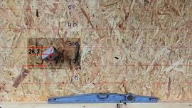
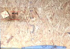
- Test case with air pistol and air rifle
Robins' formula
Robins' original book had some omitted assumptions in the formula; for example, it did not include a correction to account for a bullet impact that did not match the center of mass of the pendulum. An updated formula, with this omission corrected, was published in the Philosophical Transactions of the Royal Society the following year. Swiss mathematician Leonhard Euler, unaware of this correction, independently corrected this omission in his annotated German translation of the book.[6] The corrected formula, appearing in a 1786 edition of the book, was:
- [math]\displaystyle{ v = 614.58 g c \cdot \frac{p + b}{b i r n} }[/math]
where:
- [math]\displaystyle{ v }[/math] is the velocity of the ball in units per second
- [math]\displaystyle{ b }[/math] is the mass of the ball
- [math]\displaystyle{ p }[/math] is the mass of the pendulum
- [math]\displaystyle{ g }[/math] is the distance from pivot to the center of gravity
- [math]\displaystyle{ i }[/math] is the distance from pivot to the point of the ball's impact
- [math]\displaystyle{ c }[/math] is the chord, as measured by the ribbon described in Robins' apparatus
- [math]\displaystyle{ r }[/math] is the radius, or distance from the pivot the attachment of the ribbon
- [math]\displaystyle{ n }[/math] is the number of oscillations made by the pendulum in one minute
Robins used feet for length and ounces for mass, though other units, such as inches or pounds, may be substituted as long as consistency is maintained.[7]
Poisson's formula
A rotational inertia based formula similar to Robins' was derived by French mathematician Siméon Denis Poisson and published in The Mécanique Physique, for measuring the bullet velocity by using the recoil of the gun:
- [math]\displaystyle{ m v c f = M b k' \sqrt{g h} }[/math]
where:
- [math]\displaystyle{ m }[/math] is the mass of the bullet
- [math]\displaystyle{ v }[/math] is the velocity of the bullet
- [math]\displaystyle{ c }[/math] is the distance from pivot to the ribbon
- [math]\displaystyle{ f }[/math] is the distance from bore axis to pivot point
- [math]\displaystyle{ M }[/math] is the combined mass of gun and pendulum
- [math]\displaystyle{ b }[/math] is the chord measured by the ribbon
- [math]\displaystyle{ k' }[/math] is the radius from pivot to the center of mass of gun and pendulum (measured by oscillation, as per Robins)
- [math]\displaystyle{ g }[/math] is gravitational acceleration
- [math]\displaystyle{ h }[/math] is the distance from the center of mass of the pendulum to the pivot
[math]\displaystyle{ k' }[/math] can be calculated with the equation:
- [math]\displaystyle{ T = \pi \sqrt{\frac{k'^2}{g h}} }[/math]
Where [math]\displaystyle{ T }[/math] is half the period of oscillation.[6]
Ackley's ballistic pendulum
P.O. Ackley described how to construct and use a ballistic pendulum in 1962. Ackley's pendulum used a parallelogram linkage, with a standardized size that allowed a simplified means of calculating the velocity.[9]
Ackley's pendulum used pendulum arms of exactly 66.25 inches (168.3 cm) in length, from bearing surface to bearing surface, and used turnbuckles located in the middle of the arms to provide a means of setting the arm length precisely. Ackley recommends masses for the body of the pendulum for various calibers as well; 50 pounds (22.7 kg) for rimfire up through the .22 Hornet, 90 pounds (40.9 kg) for .222 Remington through .35 Whelen, and 150 pounds (68.2 kg) for magnum rifle calibers. The pendulum is made of heavy metal pipe, welded shut at one end, and packed with paper and sand to stop the bullet. The open end of the pendulum was covered in a sheet of rubber, to allow the bullet to enter and prevent material from leaking out.[9]
To use the pendulum, it is set up with a device to measure the horizontal distance of the pendulum swing, such as a light rod that would be pushed backwards by the rear of the pendulum as it moved. The shooter is seated at least 15 feet (5 m) back from the pendulum (reducing the effects of muzzle blast on the pendulum) and a bullet is fired into the pendulum. To calculate the velocity of the bullet given the horizontal swing, the following formula is used:[9]
- [math]\displaystyle{ V = \frac{Mp}{Mb}0.2018 D }[/math]
where:
- [math]\displaystyle{ V }[/math] is the velocity of the bullet, in feet per second
- [math]\displaystyle{ Mp }[/math] is the mass of the pendulum, in grains
- [math]\displaystyle{ Mb }[/math] is the mass of the bullet, in grains
- [math]\displaystyle{ D }[/math] is the horizontal travel of the pendulum, in inches
For more accurate calculations, a number of changes are made, both to the construction and the use of the pendulum. The construction changes involve the addition of a small box on top of the pendulum. Before weighing the pendulum, the box is filled with a number of bullets of the type being measured. For each shot made, a bullet can be removed from the box, thus keeping the mass of the pendulum constant. The measurement change involves measuring the period of the pendulum. The pendulum is swung, and the number of complete oscillations is measured over a long period of time, five to ten minutes. The time is divided by the number of oscillations to obtain the period. Once this is done, the formula [math]\displaystyle{ C = \frac{pi}{T 12} }[/math] generates a more precise constant to replace the value 0.2018 in the above equation. Just like above, the velocity of the bullet is calculated using the formula:[9]
- [math]\displaystyle{ V = \frac{Mp}{Mb}C D }[/math]
References
- ↑ "Ballistic pendulum". Encyclopædia Britannica. http://www.britannica.com/EBchecked/topic/50669/ballistic-pendulum.
- ↑ Jump up to: 2.0 2.1 2.2 Jervis-Smith, Frederick John (1911). "Chronograph". in Chisholm, Hugh. Encyclopædia Britannica. 6 (11th ed.). Cambridge University Press. p. 302.
- ↑ Gustaf Hjalmar Eneström (1903). Bibliotheca Mathematica. B. G. Teubner. https://archive.org/details/bub_gb_-bIyAQAAMAAJ.
- ↑ Scientific Papers by Peter Guthrie Tait, Vol. 2. Cambridge University Press. 1900. p. 374. https://archive.org/details/scientificpapers02taituoft.
- ↑ Benjamin Robins (1742). New Principles of Gunnery. p. 25. https://books.google.com/books?id=N3BUAAAAYAAJ&pg=PA26-IA1.
- ↑ Jump up to: 6.0 6.1 6.2 Edward John Routh (1905). The Elementary Part of A Treatise on the Dynamics of a System of Rigid Bodies. Macmillan.
- ↑ Jump up to: 7.0 7.1 Benjamin Robins; James Wilson; Charles Hutton (1805). New Principles of Gunnery. F. Wingrave. https://archive.org/details/bub_gb_3j8FAAAAMAAJ.
- ↑ "Ballistic Pendulum". Georgia State University. http://hyperphysics.phy-astr.gsu.edu/Hbase/balpen.html.
- ↑ Jump up to: 9.0 9.1 9.2 9.3 P. O. Ackley (1962). Handbook for Shooters & Reloaders, Volume I. Plaza Publishing., pages 191-195
Bibliography
- Benjamin Robins, James Wilson, Charles Hutton (1805). New Principles of Gunnery. F. Wingrave.
- "Ballistic pendulum". Encyclopædia Britannica
External links
 |


