Physics:Electrical polarity

The following outline is provided as an overview of and topical guide to electrical polarity (also called electric polarity).
Positive and negative polarity
- In electrical engineering, electrical polarity defines the direction in which the electrical current would flow once a source is connected;[1] usually used for the direct current sources, where terminals are traditionally labeled with polarity symbols + (positive) and - (negative), with the conventional current chosen to flow from the positive to negative terminal.
- By analogy, when in electronics a signal is observed across two terminals, the measurement of voltage between the terminals yields opposing signs for the positive and negative polarity.[1]
- In physics and chemistry, electric polarity defines the electric charge separation into positive and negative charges[1] within a system or molecule (for example, water molecules have unequal distribution of electrons between the oxygen and hydrogen atoms[2]). The quantitative measure of this separation is called an electric dipole moment.
- In biology, electrical polarity refers to the sign of the difference in electric potential between the parts of a living organism. For example, the inner surface of a cell membrane is usually negatively charged with respect to the outer surface (so called resting potential). When this polarity briefly reverses in a nerve, an opposite action potential is communicated over long distances.[3] The potential is maintained by a sodium–potassium pump. While sodium and potassium ions are both positively charged, their unequal concentration inside and outside of a cell causes the difference in potential.
Many electrical devices, from power sources to loudspeakers, operate in parallel. For proper operation, the connectors of these devices are usually polarized (either through the use of color-coded cables or plugs where the wires cannot be reversed).[4]
-
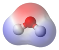 Electrical potential of the water molecule (red indicates the negative charge)
 -
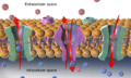 Sodium–potassium pump in a cell membrane (oversimplified)
 -
 Polarized loudspeaker connector and color-coded wire


Anode and cathode

Some electrical components are non-polar and function in the same way regardless of the direction of current through them. For example, properties of a resistor are unaffected if the wires on its terminals are swapped. Many other components, however, require a particular direction of current to operate. For terminals of such polarized electrical devices, the anode/cathode terminology is used, with anode being the connection from which the conventional current (positive charges) is flowing inside the component (thus the mnemonic ACID, anode current into device). Anode/cathode terminology is not directly tied to the electric potential of the terminals. Generally, in a battery anode has a negative potential, while in an electric load − positive. The cathode has the opposite potential:[5]
- Inside an electric battery, positive charges are flowing away from the anode (thus creating negative potential on this electrode, see the illustration) to cathode.
- In a diode, the operating current typically flows from the anode to cathode, an arrow on the diode symbol indicates the direction. There are however, exceptions, like zener diodes, that are connected in a reverse polarity, with operating current flowing from the cathode to anode. The anode/cathode terminology is also used for a similar device, a thyristor.
- Many capacitors are non-polar, but the electrolytic ones have anodes and cathodes, with anode potential required to be positive with respect to the cathode to avoid damage, even though DC current will not be flowing during the operation.
- In electrochemistry, by convention, anode is always the place for oxidation, and cathode for reduction. There are two types of cells: galvanic where spontaneous chemical reactions produce electricity (e.g., common electric batteries) and electrolytic where an external electricity source causes chemical reactions (e.g., rechargeable batteries while charging).[6] In a galvanic cell, potential on the cathode is positive with respect to the anode, in electrolytic cells cathode is negative relative to the anode.[7]
-
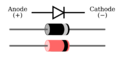 Diode symbol and typical polarity marks (bands at the cathode terminal)
 -
 Zener diode symbol
 -
 Polarity marks on an electrolytic capacitor


Transistors
While a bipolar junction transistor (BJT) can be simplistically thought of as two diodes with a shared terminal (anode for the PNP variety),[8] the transistor polarity is usually expressed based on the prevalence of charge carriers in the parts of the device: N-type for the regions where the charge flow is primarily due to the electrons (free due to the presence of dono dopants), and P-type for the regions where the flow is mostly due to electron holes (available spaces for additional electrons made possible by mixing in the acceptors).[9]
- BJT uses both types of regions (thus the adjective bipolar) and comes in either PNP or NPN polarity. The polarity is indicated by an arrow depicting the conventional current direction from the emitter to the base.[lower-alpha 1]
- Field-effect transistor (FET) uses the region of just one type (thus another name, unipolar transistor) and it can be an either N-channel or P-channel device. The wide variety of FET devices causes an elaborate set of polarity marks (conventional current always flowing down in the pictures):[10][11][12]
P-channel 


File:Mosfet P-Ch Sedra.svg 
N-channel 


File:Mosfet N-Ch Sedra.svg 
JFET MOSFET enh. MOSFET enh. (no bulk) MOSFET dep.


History
The binary ("polar") nature of electrical phenomena was known for a very long time, its similarities to the magnetic polarity were driving research on electromagnetism, with Ørsted finally succeeding in finding a link between the electricity and magnetism (Oersted's law) in 1820.[13] The use of plus and minus signs for the opposing electrical charges was introduced by Georg Christoph Lichtenberg in the 18th century. The terms positive and negative were introduced by Benjamin Franklin in 1747.[14] Franklin compared electricity to fluid, with positive indicating the excess of it, and negative identifying the deficit. Prior to Franklin, nomenclature varied, for example, du Fay called the positive charge vitreous (as it can be obtained by rubbing glass), and negative resinous (obtained by rubbing amber, resin).[15]
Berzelius, in his early 19th-century work on electrochemistry, used the term electrical polarity to explain the chemical reactions. Per Berzelius, while all atoms possessed both positive and negative polarities (electrochemical dualism, long obsolete), the balance depended on an element (with, for example, oxygen being negative and potassium positive), and the reactions were caused by the electrical attraction between the atoms.[16]
The terms anode and cathode, roughly meaning, respectively, way up and way down in Greek, were introduced by Faraday. Knowing well the Earth's magnetic field stretching North to South and assuming that it was generated by a conventional current, the direction of this current, per Ampère's circuital law, should be East to West. Sun in the East goes up and in the West down, hence the terminology.[17]
See also
- Polarized plug, a non-reversible electrical plug
- Transformer polarity, markings on the transformer indicating the mutual inductance of the coils
Notes
- ↑ The mnemonics for identifying transistors in schematics are Not Points iN (NPN) and Points iN Proudly (PNP).
References
- ↑ 1.0 1.1 1.2 Graf 1999, p. 575.
- ↑ Plopper & Ivankovic 2020, p. 214.
- ↑ Michael & Sircar 2011.
- ↑ Winer 2017, p. 481.
- ↑ anode, cathode at the Encyclopædia Britannica
- ↑ Zoski 2007, p. 6.
- ↑ Zoski 2007, p. 7.
- ↑ Razavi 2021, p. 128.
- ↑ Whitaker 1996, pp. 469–470.
- ↑ "Electronic Circuit Symbols". 9 November 2011. http://www.circuitstoday.com/electronic-circuit-symbols.
- ↑ IEEE Std 315-1975 — Graphic Symbols for Electrical and Electronics Diagrams (Including Reference Designation Letters)
- ↑ Jaeger, Richard C.; Blalock, Travis N.. "Figure 4.15 IEEE Standard MOS transistor circuit symbols". Microelectronic Circuit Design. http://highered.mcgraw-hill.com/sites/dl/free/0073191639/366537/Chapter_4.pdf#page=19.
- ↑ Whewell 1858, p. 372.
- ↑ Jensen 2005, p. 988.
- ↑ Zoski 2007, p. 3.
- ↑ Jacobsen 2003, p. xxviii.
- ↑ Couch 1924, p. 163.
Sources
- Couch, James F. (1924). "The Terms Anode and Cathode". Science (American Association for the Advancement of Science) 59 (1520): 163. ISSN 0036-8075. http://www.jstor.org/stable/1646988. Retrieved 2025-06-06.
- Graf, Rudolf F. (1999-08-11). "polarity". Modern Dictionary of Electronics. Elsevier. ISBN 978-0-08-051198-6. https://books.google.com/books?id=AYEKAQAAQBAJ&pg=PA575. Retrieved 2025-06-01.
- Jacobsen, Anja Skaar (2003). "Hans Christian Ørsted's Chemical Philosophy". H.C. Ørsted's Theory of Force: An Unpublished Textbook in Dynamical Chemistry. Kgl. Danske Videnskabernes Selskab. pp. vii-xxxii. ISBN 978-87-7876-326-6. https://books.google.com/books?id=qUpAmoyvxbcC&pg=PR28. Retrieved 2025-06-01.
- Jensen, William B. (2005). "The Origins of Positive and Negative in Electricity". Journal of Chemical Education 82 (7): 988–989. doi:10.1021/ed082p988. ISSN 0021-9584. https://homepages.uc.edu/~jensenwb/reprints/125.%20Positive%20&%20Negative.pdf. Retrieved 2025-06-01.
- Michael, Joel; Sircar, Sabyasachi (2011-01-01). "Resting Membrane Potential". Fundamentals of Medical Physiology. Thieme. ISBN 978-1-60406-275-5. https://books.google.com/books?id=Cp5WVLGpyZoC&pg=PT92. Retrieved 2025-06-01.
- Plopper, George; Ivankovic, Diana Bebek (2020-02-03). "Polarity". Principles of Cell Biology. Jones & Bartlett Learning. ISBN 978-1-284-21051-4. https://books.google.com/books?id=pKDHDwAAQBAJ&pg=PA214. Retrieved 2025-06-01.
- Razavi, Behzad (2021-04-20). Fundamentals of Microelectronics. John Wiley & Sons. ISBN 978-1-119-69514-1. https://books.google.com/books?id=8HwnEAAAQBAJ&pg=PA128. Retrieved 2025-06-07.
- Whewell, William (1858). History of Scientific Ideas. Parker. https://books.google.com/books?id=d61RAAAAcAAJ&pg=PA372. Retrieved 2025-06-01.
- Whitaker, Jerry C. (1996-12-23). The Electronics Handbook. CRC Press. ISBN 978-0-8493-8345-8. https://books.google.com/books?id=DSHSqWQXm3oC&pg=PA470. Retrieved 2025-06-07.
- Winer, E. (2017). The Audio Expert: Everything You Need to Know About Audio. Taylor & Francis. ISBN 978-1-351-84007-1. https://books.google.com/books?id=6FoPEAAAQBAJ&pg=PA481. Retrieved 2025-06-07.
- Zoski, Cynthia G. (2007-02-07). Handbook of Electrochemistry. Elsevier. ISBN 978-0-444-51958-0. https://books.google.com/books?id=2g5GJtBFwo0C&dq=electrochemistry+anode+cathode&pg=PA3. Retrieved 2025-06-06.
 |  |
