Physics:Faber-Evans model
The Faber-Evans model for crack deflection,[1][2] is a fracture mechanics-based approach to predict the increase in toughness in two-phase ceramic materials due to crack deflection.[3] The effect is named after Katherine Faber and her mentor, Anthony G. Evans, who introduced the model in 1983.[4] The Faber-Evans model is a principal strategy for tempering brittleness and creating effective ductility.[5]
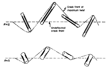
Fracture toughness is a critical property of ceramic materials, determining their ability to resist crack propagation and failure.[6] The Faber model considers the effects of different particle morphologies, including spherical, rod-shaped, and disc-shaped particles, and their influence on the driving force at the tip of a tilted and/or twisted crack. The model first suggested that rod-shaped particles with high aspect ratios are the most effective morphology for deflecting propagating cracks and increasing fracture toughness, primarily due to the twist of the crack front between particles. The findings provide a basis for designing high-toughness two-phase ceramic materials, with a focus on optimizing particle shape and volume fraction.[4]
Fracture mechanics and crack deflection
Fracture mechanics is a fundamental discipline for understanding the mechanical behavior of materials, particularly in the presence of cracks. The critical parameter in fracture mechanics is the stress intensity factor (K), which is related to the strain energy release rate (G) and the fracture toughness (Gc). When the stress intensity factor reaches the material's fracture toughness, crack propagation becomes unstable, leading to failure.
In two-phase ceramic materials, the presence of a secondary phase can lead to crack deflection, a phenomenon where the crack path deviates from its original direction due to interactions with the second-phase particles.[7] Crack deflection can lead to a reduction in the driving force at the crack tip, increasing the material's fracture toughness. The effectiveness of crack deflection in enhancing fracture toughness depends on several factors, including particle shape, size, volume fraction, and spatial distribution.
The study presents weighting functions, F(θ), for the three particle morphologies, which describe the distribution of tilt angles (θ) along the crack front:
- [math]\displaystyle{ F(\theta)_{\rm sphere}=\left ( \frac{4}{\pi} \right )\sin^2\theta \,d\theta }[/math]
- [math]\displaystyle{ F(\theta)_{\rm disk}=\left ( \frac{4}{\pi} \right )\sin^2\theta \,d\theta }[/math]
- [math]\displaystyle{ F(\theta)_{\rm rod}\approx (1.55 + 1.10\theta - 2.42\theta^2 + 1.78\theta^3)sin\theta \,cos\theta \,d\theta }[/math]
The weighting functions are used to determine the net driving force on the tilted crack for each morphology. The relative driving force for spherical particles is given by:
- [math]\displaystyle{ \left \langle {G} \right \rangle_{sphere}^t/G_\infty=\left ( \frac{4}{\pi} \right )\sin^2\theta[(k_1^t)^2+(k_2^t)]d\theta }[/math]
where [math]\displaystyle{ k_i=k_i/K_1 }[/math] and [math]\displaystyle{ \left \langle {G} \right \rangle^t }[/math] prescribes the strain energy release rate only for that portion of the crack front which tilts. To characterize the entire crack front at initial tilt, [math]\displaystyle{ \left \langle {G} \right \rangle^t }[/math] must be qualified by the fraction of the crack length intercepted and superposed on the driving force that derives from the remaining undeflected portion of the crack. The resultant toughening increment, derived directly from the driving forces, is given by:
- [math]\displaystyle{ (G_{\rm c}^{t})_{sphere}=(1+0.87V_f)G_{\rm c}^{m} }[/math]
- [math]\displaystyle{ (G_{\rm c}^{t})_{rod}\approx(1+V_f(0.6+0.007(H/r)-0.0001(H/r)^2)G_{\rm c}^{m} }[/math]
- [math]\displaystyle{ (G_{\rm c}^{t})_{disk}=[1+0.56V_f(r/t)]G_{\rm c}^{m} }[/math]
where [math]\displaystyle{ G_{\rm c}^{m} }[/math] represents the fracture toughness of the matrix material without the presence of any reinforcing particles, [math]\displaystyle{ V_f }[/math] is the volume fraction of spheres, [math]\displaystyle{ (H/r) }[/math] relates the rod length [math]\displaystyle{ H }[/math] to its radius, [math]\displaystyle{ r }[/math], and [math]\displaystyle{ (r/t) }[/math] is the ratio of the disc radius, [math]\displaystyle{ r }[/math], to its thickness, [math]\displaystyle{ t }[/math].
Spatial location and orientation of particles
The spatial location and orientation of adjacent particles play a crucial role in determining whether the inter-particle crack front will tilt or twist. If adjacent particles produce tilt angles of opposite sign, twist of the crack front will result. Conversely, tilt angles of like sign at adjacent particles cause the entire crack front to tilt. Therefore, to evaluate the toughening increment, all possible particle configurations must be considered.
For spherical particles, the average twist angle is determined by the mean center-to-center nearest neighboring distance, [math]\displaystyle{ \Delta }[/math], between particles with spheres of radius r:[8]
[math]\displaystyle{ \frac{\Delta}{r}=\frac{e^{8V_f}}{V_f^{1/3}}\int_{8V_f}^{\infty} x^{1/3}e^{-x}dx }[/math]
The maximum twist angle occurs when the particles are nearly co-planar with the crack, given by:
[math]\displaystyle{ \phi_{max}=\sin^{-1}\left ( \frac{2r}{\Delta} \right ) }[/math]
and depends exclusively on the volume fraction.
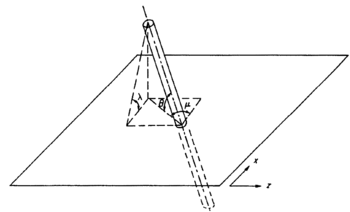
For rod-shaped particles, the analysis of crack front twist is more complex due to difficulties in describing the rod orientation with respect to the crack front and adjacent rods. The twist angle, [math]\displaystyle{ \phi }[/math], is determined by the effective tilt angle, [math]\displaystyle{ \lambda }[/math], and the inter-particle spacing between randomly arranged rod-shaped particles. The twist of the crack front is influenced not only by the volume fraction of rods but also by the ratio of the rod length to radius:
[math]\displaystyle{ \phi=\tan^{-1}\left \{ \frac{\alpha\sin\theta_1+(1-\beta)\sin\theta_2}{\Delta'} \right \} }[/math]
where [math]\displaystyle{ \Delta' }[/math] represents the dimensionless effective inter-particle spacing between two adjacent rod-shaped particles.
Morphology and volume effects on fracture toughness
The analysis reveals that rod-shaped particles with high aspect ratios are the most effective morphology for deflecting propagating cracks, with the potential to increase fracture toughness by up to four times.[4] This toughening arises primarily from the twist of the crack front between particles. Disc-shaped particles and spheres are less effective in increasing fracture toughness.
For disc-shaped particles with high aspect ratios, initial crack front tilt can provide significant toughening, although the twist component still dominates. In contrast, neither sphere nor rod particles derive substantial toughening from the initial tilting process. As the volume fraction of particles increases, an asymptotic toughening effect is observed for all three morphologies at volume fractions above 0.2. For spherical particles, the interparticle spacing distribution has a significant impact on toughening, with greater enhancements when spheres are nearly contacting and twist angles approach π/2.
The Faber-Evans model suggests that rod-shaped particles with high aspect ratios are the most effective morphology for deflecting propagating cracks and increasing fracture toughness, primarily due to the twist of the crack front between particles. Disc-shaped particles and spheres are less effective in enhancing toughness. However, the interparticle spacing distribution plays a significant role in the toughening by spherical particles, with greater toughening achieved when spheres are nearly contacting.
In designing high-toughness two-phase ceramic materials, the focus should be on optimizing particle shape and volume fraction. The model proved that ideal second phase should be chemically compatible and present in amounts of 10 to 20 volume percent, with particles having high aspect ratios, particularly those with rod-shaped morphologies, providing the maximum toughening effect.[9] This model is often used in the development of advanced ceramic materials with improved performance when the factors that contribute to the increase in fracture toughness is a consideration.[10][11]
See also
References
- ↑ Parmigiani, J. P.; Thouless, M. D. (2006-02-01). "The roles of toughness and cohesive strength on crack deflection at interfaces" (in en). Journal of the Mechanics and Physics of Solids 54 (2): 266–287. doi:10.1016/j.jmps.2005.09.002. ISSN 0022-5096. Bibcode: 2006JMPSo..54..266P. https://www.sciencedirect.com/science/article/pii/S0022509605001730.
- ↑ Ye, C. C.; Ru, H. Q.; Qin, Z. B.; Zhao, S. W.; Jia, H. S.; Chen, D. L. (2020-03-27). "Silicon nitride composites with magnesia and alumina additives: Toughening mechanisms and mechanical properties" (in en). Materials Science and Engineering: A 779: 139140. doi:10.1016/j.msea.2020.139140. ISSN 0921-5093. https://www.sciencedirect.com/science/article/pii/S0921509320302276.
- ↑ Faber, K. T.; Evans, A. G. (1983-04-01). "Crack deflection processes—II. Experiment" (in en). Acta Metallurgica 31 (4): 577–584. doi:10.1016/0001-6160(83)90047-0. ISSN 0001-6160. https://dx.doi.org/10.1016/0001-6160%2883%2990047-0.
- ↑ 4.0 4.1 4.2 Faber, K. T.; Evans, A. G. (1983-04-01). "Crack deflection processes—I. Theory" (in en). Acta Metallurgica 31 (4): 565–576. doi:10.1016/0001-6160(83)90046-9. ISSN 0001-6160. https://dx.doi.org/10.1016/0001-6160%2883%2990046-9.
- ↑ Salman, O. U.; Truskinovsky, L. (2021-09-01). "De-localizing brittle fracture" (in en). Journal of the Mechanics and Physics of Solids 154: 104517. doi:10.1016/j.jmps.2021.104517. ISSN 0022-5096. Bibcode: 2021JMPSo.15404517S. https://www.sciencedirect.com/science/article/pii/S0022509621001812.
- ↑ Gogotsi, George A (2003-01-01). "Fracture toughness of ceramics and ceramic composites" (in en). Ceramics International 29 (7): 777–784. doi:10.1016/S0272-8842(02)00230-4. ISSN 0272-8842. https://www.sciencedirect.com/science/article/pii/S0272884202002304.
- ↑ Green, David J.; Nicholson, Patrick S.; Embury, J. David (1979-06-01). "Fracture of a brittle particulate composite" (in en). Journal of Materials Science 14 (6): 1413–1420. doi:10.1007/BF00549316. ISSN 1573-4803. Bibcode: 1979JMatS..14.1413G. https://doi.org/10.1007/BF00549316.
- ↑ Bansal, P. P.; Ardell, A. J. (1972-04-01). "Average nearest-neighbor distances between uniformly distributed finite particles" (in en). Metallography 5 (2): 97–111. doi:10.1016/0026-0800(72)90048-1. ISSN 0026-0800. https://dx.doi.org/10.1016/0026-0800%2872%2990048-1.
- ↑ Zhang, Honggang; Zhang, Nan; Fang, Fengzhou (2021-11-01). "Study of ion transportation and electrodeposition under hybrid agitation for electroforming of variable aspect ratios micro structures" (in en). Precision Engineering 72: 122–143. doi:10.1016/j.precisioneng.2021.04.008. ISSN 0141-6359.
- ↑ Liu, Haiyan; Weisskopf, Karl-L.; Petzow, Gunter (1989). "Crack Deflection Process for Hot-Pressed Whisker-Reinforced Ceramic Composites" (in en). Journal of the American Ceramic Society 72 (4): 559–563. doi:10.1111/j.1151-2916.1989.tb06175.x. ISSN 0002-7820. https://onlinelibrary.wiley.com/doi/10.1111/j.1151-2916.1989.tb06175.x.
- ↑ Carter, David H.; Hurley, George F. (1987). "Crack Deflection as a Toughening Mechanism in SiC-Whisker-Reinforced MoSi2" (in en). Journal of the American Ceramic Society 70 (4): C–79–C-81. doi:10.1111/j.1151-2916.1987.tb04992.x. ISSN 0002-7820. https://onlinelibrary.wiley.com/doi/10.1111/j.1151-2916.1987.tb04992.x.
 |


