Physics:Friction-plate electromagnetic couplings
Electromagnetic clutches and brakes operate electrically, but transmit torque mechanically. This is why they used to be referred to as electro-mechanical clutches or brakes. Over the years, EM became known as electromagnetic versus electro mechanical, referring more about their actuation method versus physical operation. Since the clutches started becoming popular over 60 years ago, the variety of applications and brake and clutch designs has increased dramatically, but the basic operation remains the same.
This article is about the working principles of single face friction plate clutches and brakes. In this article, clutches and brakes are referred to as (mechanical) couplings.
Construction
A horseshoe magnet (A-1) has a north and south pole. If a piece of carbon steel contacts both poles, a magnetic circuit is created. In an electromagnetic coupling, the north and south pole is created by a coil shell and a wound coil.
-
 A-1 Horseshoe magnet
 -
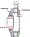
 B-1 Electromagnetic clutch
 -
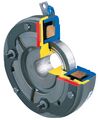 A-2 Ogura Industrial Typical 2 pole clutch
 -
 A-4 Triple flux clutch
 -
 A-6 Double Flux clutch
 -
 A-7 Triple flux rotor with banana slots and bridges
 -
 A-3 Electromagnetic brake


Clutches
In a clutch, (B1) when power is applied, a magnetic field is created in the coil (A2 blue). This field (flux) overcomes an air gap between the clutch rotor (A2 yellow) and the armature (A2 red). This magnetic attraction, pulls the armature in contact with the rotor face. The frictional contact, which is being controlled by the strength of the magnetic field, is what causes the rotational motion to start.
The torque comes from the magnetic attraction, of the coil and the friction between the steel of the armature and the steel of the clutch rotor or brake field. For many industrial couplings, friction material is used between the poles. The material is mainly used to help decrease the wear rate, but different types of material can also be used to change the coefficient of friction (torque for special applications). For example, if the coupling is required to have an extended time to speed/stop or slip time, a low coefficient friction material can be used. Conversely, if a coupling is required to have a slightly higher torque (mostly for low rpm applications), a high coefficient friction material can be used.[1]
The electromagnetic lines of flux have to attract and pull the armature in contact with it to complete engagement. Most industrial couplings use what is called a single flux, two pole design (A-2). Mobile clutches of other specialty electromagnetic clutches can use a double or triple flux rotor (A-4). The double or trip flux refers to the number of north–south flux paths (A-6), in the rotor and armature. These slots (banana slots) (A-7) create an air gap which causes the flux path to take the path of least resistance when the faces are engaged. This means that, if the armature is designed properly and has similar banana slots, what occurs is a leaping of the flux path, which goes north south, north south (A-6). By having more points of contact, the torque can be greatly increased. In theory, if there were 2 sets of poles at the same diameter, the torque would double in a clutch. Obviously, that is not possible to do, so the points of contact have to be at a smaller inner diameter. Also, there are magnetic flux losses because of the bridges between the banana slots. But by using a double flux design, a 30–50% increase in torque, can be achieved, and by using a triple flux design, a 40–90% in torque can be achieved. This is important in applications where size and weight are critical, such as automotive requirements.[2]
The coil shell is made with carbon steel that has a combination of good strength and good magnetic properties. Copper (sometimes aluminum) magnet wire, is used to create the coil, which is held in shell either by a bobbin or by some type of epoxy/adhesive.[3]
To help increase life in applications, friction material is used between the poles. This friction material is flush with the steel on the coil shell or rotor, since if the friction material was not flush, good magnetic traction could not occur between the faces. Some people look at electromagnetic clutches and mistakenly assume that, since the friction material is flush with the steel, that the clutch has already worn down, but this is not the case. Clutches used in most mobile applications, (automotive, agriculture, construction equipment) do not use friction material. Their cycle requirements tend to be lower than industrial clutches, and their cost is more sensitive. Also, many mobile clutches are exposed to outside elements, so by not having friction material, it eliminates the possibility of swelling (reduced torque), that can happen when friction material absorbs moisture.[4]
Brakes
In an electromagnetic brake, the north and south pole is created by a coil shell and a wound coil. In a brake, the armature is being pulled against the brake field. (A-3) The frictional contact, which is being controlled by the strength of the magnetic field, is what causes the rotational motion to stop.
Basic operation
Engagement of clutches
The clutch has four main parts: field, rotor, armature, and hub (output) (B1). When voltage is applied the stationary magnetic field generates the lines of flux that pass into the rotor. (The rotor is normally connected to the part that is always moving in the machine.) The flux (magnetic attraction) pulls the armature in contact with the rotor (the armature is connected to the component that requires the acceleration), as the armature and the output start to accelerate. Slipping between the rotor face and the armature face continues until the input and output speed is the same (100% lockup). The actual time for this is quite short, between 1/200th of a second and 1 second.
Engagement of brakes
There are three parts to an electromagnetic brake: field, armature, and hub (which is the input on a brake) (A-3). Usually the magnetic field is bolted to the machine frame (or uses a torque arm that can handle the torque of the brake). So when the armature is attracted to the field the stopping torque is transferred into the field housing and into the machine frame decelerating the load. This can happen very fast (.1-3sec).
Disengagement
Disengagement is very simple. Once the field starts to degrade, flux falls rapidly and the armature separates. One or more springs hold the armature away from its corresponding contact surface at a predetermined air gap.
Voltage/current and the magnetic field

If a piece of copper wire was wound, around the nail and then connected to a battery, it would create an electro magnet. The magnetic field that is generated in the wire, from the current, is known as the "right hand thumb rule". (V-1) The strength of the magnetic field can be changed by changing both wire size and the amount of wire (turns). EM couplings are similar; they use a copper wire coil (sometimes aluminum) to create a magnetic field.
The fields of EM couplings can be made to operate at almost any DC voltage, and the torque produced by the clutch or brake will be the same, as long as the correct operating voltage and current is used with the correct coupling. If a 90 V clutch, a 48 V clutch and a 24 V clutch, all being powered with their respective voltages and current, all would produce the same amount of torque. However, if a 90 V clutch had 48 V applied to it, this would get about half of the correct torque output of that clutch. This is because voltage/current is almost linear to torque in DC electromagnetic couplings.
A constant power supply is ideal if accurate or maximum torque is required from a coupling. If a non-regulated power supply is used, the magnetic flux will degrade, as the resistance of the coil goes up. Basically, the hotter the coil gets the lower the torque will be, by about an average of 8% for every 20 °C. If the temperature is fairly constant, but there may not be enough service factor in your design for minor temperature fluctuation. Over-sizing, the clutch would compensate for minor flux. This will allow the use a rectified power supply which is far less expensive than a constant current supply.
Based on V = I × R, as resistance increases available current falls. An increase in resistance, often results from rising temperature as the coil heats up, according to: Rf = Ri × [1 + αCu × (Tf - Ti)] Where Rf = final resistance, Ri = initial resistance, αCu = copper wire's temperature coefficient of resistance, 0.0039 °C-1, Tf = final temperature, and Ti = initial temperature.
Engagement time
There are actually two engagement times to consider in an electromagnetic coupling. The first one is the time it takes for a coil to develop a magnetic field, strong enough to pull in an armature. Within this, there are two factors to consider. The first one is the amount of ampere turns in a coil, which will determine the strength of a magnetic field. The second one is air gap, which is the space between the armature and the coil shell or rotor. Magnetic lines of flux diminish quickly in the air. The further away the attractive piece is from the coil, the longer it will take for that piece to actually develop enough magnetic force to be attracted and pull in to overcome the air gap. For very high cycle applications, floating armatures can be used that rest lightly against the coil shell or rotor. In this case, the air gap is zero; but, more importantly the response time is very consistent since there is no air gap to overcome. Air gap is an important consideration especially with a fixed armature design because as the unit wears over many cycles of engagement the armature and the rotor will create a larger air gap which will change the engagement time of the clutch. In high cycle applications, where registration is important, even the difference of 10–15 milliseconds can make a difference, in registration of a machine. Even in a normal cycle application, this is important because a new machine that has accurate timing can eventually see a "drift" in its accuracy as the machine gets older.
The second factor in figuring out response time of a coupling is actually much more important than the magnet wire or the air gap. It involves calculating the amount of inertia that the coupling needs to accelerate. This is referred to as "time to speed". In reality, this is what the end-user is most concerned with. Once it is known how much inertia is present for the clutch to start or for the brake to stop, then the torque can be calculated and the appropriate size of clutch can be chosen.
Most CAD systems can automatically calculate component inertia, but the key to sizing a brake or clutch is calculating how much inertia is reflected back to the clutch or brake. To do this, engineers use the formula: T = (WK2 × ΔN) / (308 × t) Where T = required torque in lb-ft, WK2 = total inertia in lb-ft2, ΔN = change in the rotational speed in rpm, and t = time during which the acceleration or deceleration must take place.
There are also online sites that can help confirm how much torque is required to decelerate or accelerate a given amount of inertia over a specific time. Remember to make sure that the torque chosen, for the clutch or brake, should be after it has been burnished.
Burnishing
Burnishing is the wearing or mating of opposing surfaces. When the armature and rotor or brake faces are produced, the faces are machined as flat as possible. (Some manufacturers also lightly grind the faces to get them smoother.) But even with that the machining process leaves peaks and valleys on the surface of the steel. When a new "out of the box" coupling is initially engaged most peaks on both mating surfaces touch which means that the potential contact area can be significantly reduced. In some cases, an out of box coupling can have only 50% of its torque rating.
Burnishing is the process of cycling the coupling to wear down those initial peaks, so that there is more surface contact between the mating faces.
Even though burnishing is required to get full torque out of the coupling, it may not be required in all applications. Simply put, if the application torque is lower than the initial out of box torque of the coupling, burnishing is not required however, if the torque required is higher, then burnishing needs to be done. In general, this tends to be required more on higher torque couplings than on smaller torque couplings.
The process involves cycling the coupling a number of times at a lower inertia, lower speed or a combination of both. Burnishing can require anywhere from 20 to over 100 cycles depending upon the size of a coupling and the amount of initial torque required. For bearing mounted couplings, where the rotor and armature are connected and held in place via a bearing, burnishing does not have to take place on the machine. It can be done individually on a bench or in a group burnishing station. If a clutch has a separate armature and rotor (two piece unit) burnishing is done as a matched set, to make sure proper torque is achieved. Similarly, two-piece brakes that have separate armatures should be burnished on a machine rather than a bench because any change in the mounting tolerance as that brake is mounted to the machine may shift the alignment so the burnishing lines on the armature, rotor or brake face may be off, slightly preventing that brake from achieving full torque. Again, the difference is only slight so this would only be required in a very torque sensitive application.
Torque
Burnishing can affect initial torque of a coupling but there are also factors that affect the torque performance of a coupling in an application. The main one is voltage/current. In the voltage/current section, it was shown why a constant current supply is important to get full torque out of a coupling.
When considering torque, the question of using dynamic or static torque for the application is key. For example, if a machine is running at a relatively low rpm (5–50 depending upon size) then dynamic torque is not a consideration since the static torque rating of the coupling will come closest to where the application is running. However, if a machine is running at 3,000rpm and the same full torque is required the result will not be the same because of the difference between static and dynamic torques. Almost all manufacturers put the static rated torque for their couplings in their catalog. If a specific response time is needed, the dynamic torque rating for a particular coupling at a given speed is required. In many cases, this can be significantly lower. Sometimes it can be less than ½ of the static torque rating. Most manufacturers publish torque curves showing the relationship between dynamic and static torque for a given series of couplings. (T-1)

Over-excitation
Over-excitation is used to achieve a faster response time. It's when a coil momentarily receives a higher voltage than its nominal rating. To be effective the over excitation voltage must be significantly, but not to the point of diminishing returns, higher than the normal coil voltage. Three times the voltage typically gives around ⅓ faster response. Fifteen times the normal coil voltage will produce a 3 times faster response time. For example, a clutch coil that was rated for 6 V would need to put in 90 V to achieve the 3 times factor.
With over-excitation the in-rush voltage is momentary. Although it would depend upon the size of the coil the actual time is usually only a few milliseconds. The theory is, for the coil to generate as much of a magnetic field as quickly as possible to attract the armature and start the process of acceleration or deceleration. Once the over excitation is no longer required the power supply to the clutch or brake would return to its normal operating voltage. This process can be repeated a number of times as long as the high voltage does not stay in the coil long enough to cause the coil wire to overheat.
Wear
It is very rare that a coil would just stop working in an electromagnetic coupling . Typically, if a coil fails it is usually due to heat which has caused the insulation of the coil wire to break down. The heat can be caused by high ambient temperature, high cycle rates, slipping or applying too high of a voltage. Bushings can be used in some clutches that have low speed, low side loads or low operating hours. At higher loads and speeds, bearing mounted field/rotors and hubs are a better option. Most brakes are flanged mounted and have bearings but some brakes are bearing mounted. Like the coils, unless bearings are stressed beyond their physical limitations or become contaminated, they tend to have a long life and they are usually the second item to wear out.
The main wear in electromagnetic couplings occurs on the faces of the mating surfaces. Every time a coupling is engaged during rotation a certain amount of energy is transferred as heat. The transfer, which occurs during rotation wears both the armature and the opposing contact surface. Based upon the size of the clutch or brake, the speed and the inertia, wear rates will differ. For example, a machine that was running at 500 rpm with a clutch and is now sped up to 1000 rpm would have its wear rate significantly increased because the amount of energy required to start the same amount of inertia is a lot higher at the higher speed. With a fixed armature design a coupling will eventually simply cease to engage. This is because the air gap will eventually become too large for the magnetic field to overcome. Zero gap or auto wear armatures can wear to the point of less than one half of its original thickness, which will eventually cause missed engagements.
Designers can estimate life from the energy transferred each time the brake or clutch engages. Ee = [m × v2 × τd] / [182 × (τd + τl)] Where Ee = energy per engagement, m = inertia, v = speed, τd = dynamic torque, and τl = load torque. Knowing the energy per engagement lets the designer calculate the number of engagement cycles the clutch or brake will last: L = V / (Ee × w) Where L = unit life in number of cycles, V = total engagement area, and w = wear rate.
Backlash
Some applications require very tight precision between all components. In these applications, even 1° of movement between the input and the output when a coupling is engaged can be a problem. This is true in many robotic applications. Sometimes the design engineers will order clutches or brakes with zero backlash but then key them to the shafts so although the clutch or brake will have zero backlash there's still minimal movement occurring between the hub or rotor in the shaft.
Most applications, however, do not need true zero backlash and can use a spline type connection. Some of these connections between the armature and the hub are standard splines others are hex or square hub designs. The spline will have the best initial backlash tolerance. Typically around 2° but the spline and the other connection types can wear over time and the tolerances will increase.
Environment / contamination
As couplings wear they create wear particles. In some applications such as clean rooms or food handling this dust could be a contamination problem so in these applications the coupling should be enclosed to prevent the particles from contaminating other surfaces around it. But a more likely scenario is that the coupling has a better chance of getting contaminated from its environment. Obviously oil or grease should be kept away from the contact surface because they would significantly reduce the coefficient of friction which could drastically decrease the torque potentially causing failure. Oil mist or lubricated particles can also cause surface contamination. Sometimes paper dust or other contamination can fall in between the contact surfaces. This can also result in a loss of torque. If a known source of contamination is going to be present many clutch manufactures offer contamination shields that prevent material from falling in between the contact surfaces.
In clutches and brakes that have not been used in a while, rust can develop on the surfaces. But in general, this is normally not a major concern since the rust is worn off within a few cycles and there is no lasting impact on the torque.
See also
References
- ↑ Flemming, Frank (7 July 2009). Shapiro, Jessica. ed. "Basics of Electromagnetic Clutches and Brakes". Machine Design: 57–58. Archived from the original on 2010-02-15. https://web.archive.org/web/20100215162059/http://www.ogura-clutch.com/pdfs/The%20Basics%20of%20Electromagnetic%20Clutches%20and%20Brakes.pdf. Retrieved 23 October 2013.
- ↑ Flemming, Frank (5 August 1999). Kren, Lawrence. ed. "Getting a Handle on Inertia". Machine Design: 92–93. Archived from the original on 2010-02-16. https://web.archive.org/web/20100216152634/http://www.ogura-clutch.com/pdfs/Gettingahandleoninertia.pdf. Retrieved 23 October 2013.
- ↑ Flemming, Frank (9 September 1999). Zalud, Todd. ed. "Getting a Grip on Clutch and Brake Selection". Machine Design: 83–86. Archived from the original on 2010-02-17. https://web.archive.org/web/20100217002307/http://www.ogura-clutch.com/pdfs/Gettingagriponclutchbrakeselection.pdf. Retrieved 23 October 2013.
- ↑ Auguston, Karen; Flemming, Frank (September 1999). "Floating Armature Speeds Response". Global Design News: 46–47. Archived from the original on 2010-02-17. https://web.archive.org/web/20100217002422/http://www.ogura-clutch.com/pdfs/floatingarmature.pdf. Retrieved 23 October 2013.
External links
- The Basics of Electromagnetic Clutches and Brakes
- Getting A Grip on Clutch and Brake Selection
- Floating Armature revs up Clutch Brake System[yes|permanent dead link|dead link}}]
- Inertia-calc.com Inertia calculator
de:Magnetkupplung
 |
