Physics:Integrated gasification fuel cell cycle
Lower-temperature fuel cell types such as the proton exchange membrane fuel cell, phosphoric acid fuel cell, and alkaline fuel cell require pure hydrogen as fuel, typically produced from external reforming of natural gas. However, fuels cells operating at high temperature such as the solid oxide fuel cell (SOFC) are not poisoned by carbon monoxide and carbon dioxide, and in fact can accept hydrogen, carbon monoxide, carbon dioxide, steam, and methane mixtures as fuel directly, because of their internal shift and reforming capabilities.[1] This opens up the possibility of efficient fuel cell-based power cycles consuming solid fuels such as coal and biomass, the gasification of which results in syngas containing mostly hydrogen, carbon monoxide and methane which can be cleaned and fed directly to the SOFCs without the added cost and complexity of methane reforming, water gas shifting and hydrogen separation operations which would otherwise be needed to isolate pure hydrogen as fuel. A power cycle based on gasification of solid fuel and SOFCs is called an Integrated Gasification Fuel Cell (IGFC) cycle; the IGFC power plant is analogous to an integrated gasification combined cycle power plant, but with the gas turbine power generation unit replaced with a fuel cell (high temperature type such as SOFC) power generation unit.[2] By taking advantage of intrinsically high energy efficiency of SOFCs and process integration, exceptionally high power plant efficiencies are possible. Furthermore, SOFCs in the IGFC cycle can be operated so as to isolate a carbon dioxide-rich anodic exhaust stream, allowing efficient carbon capture to address greenhouse gas emissions concerns of coal-based power generation.
Process Configuration
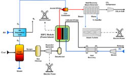
The IGFC system combines use of SOFCs as a topping cycle to the gas turbine or heat recovery steam generator-based bottoming cycle. Typical major components of the IGFC system, this one centered on a SOFC module running at atmospheric pressure, are identified in the simplified cycle diagram.
The system fuel as depicted is coal, converted to syngas by the gasifier, which is then supplied to the SOFC module after cleanup and pressure reduction. The syngas pressure reduction step is accomplished in this system concept by an expander/generator, which thereby produces part of the cycle's gross power generation. Oxygen for the coal gasification process is provided by a conventional air separation unit, and steam for the gasifier is raised by power system heat and recycled water. Note that the SOFC module is configured to maintain the anode and cathode off-gas streams separated, and the anode off-gas, which contains some electrochemically-unreacted hydrogen and carbon monoxide, is combusted to completion at the oxy-combustor. Maintaining separation of the off-gas streams restricts the large atmospheric nitrogen content to the cathode side, and simplifies the CO2 capture process to anode off-gas cooling, water-vapor condensation, CO2 drying, and CO2 compression. Compressed CO2 is suitable for carbon utilization or storage (CUS) as appropriate. Heat recovered from the anode-side process can be used by a power-generating bottoming cycle consisting of a heat recovery steam generator and steam turbine. On the cathode side, process air for the SOFC electrochemical process and for module cooling is provided by an air blower; heat can be recovered from the hot cathode off-gas stream to preheat the process air as needed, and for the generation of additional power. Due to the inherently efficient SOFC, and to using recovered SOFC exhaust heat to generate additional electric power, an IGFC system is capable of operating at a high electric efficiency that significantly exceeds those associated with conventional pulverized coal and integrated gasification combined cycle power systems. IGFC efficiency margins considered achievable, based upon the U.S. Department of Energy's National Energy Technology Laboratory comparative studies of advanced power systems, are apparent in the table provided in subsequent discussion.
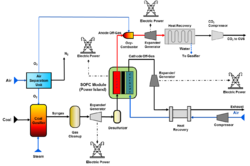
Improvement in the IGFC cycle efficiency is possible by pressurized operation of the SOFCs, as depicted in the diagram of IGFC with pressurized SOFC cycle. The process is basically similar to the atmospheric-pressure cycle, but it would run the SOFC module at elevated pressure, achieving an SOFC voltage boost, and would replace the cathode-side process-air blower with an air compressor. Also, an expander/generator would be installed in the cathode off-gas stream to reduce gas pressures and generate additional power (this tends to drop the temperature of the gases so much that steam generation to run a steam turbine is not a viable option). Optionally, an expander/generator set could also be placed in the anode off-gas stream, just downstream of the oxy-combustor, and ahead of off-gas heat recovery.
Gasification Choices for IGFC
Multiple types of solid fuel gasifiers are commercially available for coal, petcoke, and biomass gasification. Designs vary depending on fuel and intended application. As a result, they can differ in the composition of the syngas produced and the efficiency with which they convert coal energy content to syngas energy content - a performance parameter typically termed cold gas efficiency.[3] The gasifiers also vary in their main operating parameters – e.g., process temperature, pressure, and demands for oxygen and steam. For power systems based upon the integration of coal gasification and SOFC technologies, these parameters, particularly cold gas efficiency and the oxygen and steam demands, will affect electricity production efficiency.
Gasifiers are of three main types – entrained flow, moving bed, and fluidized bed.[4] Entrained flow gasifiers (e.g., GE Energy, Shell, E-Gas™, Siemens) could attract early interest for fuel cell power system applications because they are relatively well developed and are used in current integrated gasification combined cycle power system designs and applications. Entrained flow gasification typically proceeds at relatively high process temperatures, requires oxygen input at relatively high rates, steam input at low to moderate rates, and it produces a syngas product with very small methane content, typically less than 1% (vol). Cold gas efficiencies for entrained flow gasification are usually in the 80% range. The moving-bed gasifier (e.g., Lurgi) operates at moderate temperature levels, and with moderate oxygen and steam supply requirements. The cold gas efficiency achieved by this gasifier is higher, circa 90%, and its syngas product stream will have methane content nominally in the 4-5% (vol) range.[5] Fluidized-bed gasification (e.g., KBR Transport) proceeds with similar characteristics, but will exhibit somewhat lower syngas methane content, typically in the 2-3% (vol) range.[6]
Of particular interest to the SOFC-based IGFC power system is catalytic coal gasification, because of the characteristically high methane content of its resultant syngas. This process experienced development in the 1980s for synthetic natural gas production purposes. Compared to conventional gasification summarized above, a catalytic gasifier would require less oxygen input, run at a lower process temperature, and produce a syngas stream with a higher methane concentration [15-30% (vol)], in addition to hydrogen and carbon monoxide.[7] With its lower operating temperature, a relatively high cold gas efficiency of at least 90% is projected for catalytic gasification, and this characteristic, as well as the process need for less oxygen input, would directly support high-efficiency IGFC power system operation. Furthermore, internal reformation of the substantial methane content of its syngas within the SOFC module can be used by design to assist module cooling, and can thereby lead to reductions in the parasitic power demand associated with cooling air supply. The SOFC electric power generator module in an IGFC system could conceivably be fueled with syngas supplied by any of the available conventional coal gasifiers, and studies indicate that power system electric efficiencies in the 45-50% range are achievable, depending on whether the power system uses atmospheric-pressure or pressurized SOFC modules. However, from the efficiency viewpoint particularly, the preferred coal gasification approach for the application is catalytic. Using that technology, IGFC system efficiencies in 56-60% range are projected, again depending on SOFC module pressurization. Estimates and comparisons are tabulated below.
| Power System Type | Efficiency Estimate (Net power/Coal HHV basis)† |
|---|---|
| Pulverized Coal | 28[8] |
| IGCC | 33[8] |
| IGFC, Conventional Coal Gasification | |
| Atmospheric Pressure SOFC | 47[2] |
| Pressurized SOFC | 50[2] |
| IGFC, Catalytic Coal Gasification | |
| Atmospheric Pressure SOFC | 56[2] |
| Pressurized SOFC | 60[2] |
† The efficiency estimates include the effects of parasitic power loads due to CO2 compression for carbon sequestration/storage.
In addition to high power system efficiencies, studies[2][9] also project significant IGFC system power plant capital cost, cost of electricity, and net water usage advantages: IGFC electric power systems integrating catalytic coal gasification with SOFC module designs that separate anode and cathode off-gas streams, and feature methane reformation-augmented SOFC cooling, would operate cleanly with very high electric efficiencies, while providing for high levels of carbon capture, and requiring low net water input.
Carbon Dioxide Capture in IGFC Cycles
SOFC design and IGFC process configuration can greatly simplify the capture of carbon dioxide,[10] which will increasingly be demanded for low greenhouse gas emissions of most fossil-fuel utilization processes. In conventional combustion, fuel is burned in air, resulting in exhaust gases containing large amount of nitrogen from which capture of a pure carbon dioxide stream (needed for storage of carbon in greenhouse gas emissions control scenarios) is inefficient. In oxy-combustion, oxygen is extracted from air and used for fuel combustion, resulting in exhaust gases uncontaminated with nitrogen from which capture of a pure carbon dioxide stream is efficient. However, a large energy penalty for doing the air separation required for isolating the oxygen stream in the first place is incurred. In contrast, for SOFC function neither inefficient carbon capture from exhaust gases nor air separation is required: the only required interaction of the anode and cathode reactant streams is the transfer of oxygen from cathode side (air) to anode side (fuel). All carbon, excepting the negligible amount in atmospheric air coming in at the cathode, will enter the module with fuel on the anode side, and it must exit the anode as carbon dioxide and carbon monoxide. By designing the SOFC module to keep anode and cathode off-gas streams separated, dilution of that carbon-rich stream with atmospheric nitrogen from the cathode side is avoided, allowing simple and inexpensive carbon dioxide separation and capture downstream.
See also
- Solid Oxide Fuel Cell
- Integrated Gasification Combined Cycle
References
- ↑ Giddey, S.; Badwal, S.P.S.; Kulkarni, A.; Munnings, C. (June 2012). "A comprehensive review of direct carbon fuel cell technology". Progress in Energy and Combustion Science 38 (3): 360–399. doi:10.1016/j.pecs.2012.01.003.
- ↑ 2.0 2.1 2.2 2.3 2.4 2.5 "Analysis of Integrated Gasification Fuel Cell Plant Configurations, DOE/NETL-2011/1482". National Energy Technology Laboratory. February 2011. http://www.netl.doe.gov/File%20Library/Research/Energy%20Analysis/Coal/IGFC_FR_20110225.pdf.
- ↑ Higman, Christopher; van der Burgt, Maarten (2008). Gasification (Second ed.). Elsevier, Inc.. pp. 28–30. ISBN 978-0-7506-8528-3. https://archive.org/details/gasification00higm_662.
- ↑ "Commercial Gasifiers-Types of Gasifiers". National Energy Technology Laboratory, U.S. Department of Energy. http://www.netl.doe.gov/research/Coal/energy-systems/gasification/gasifipedia/types-gasifiers.
- ↑ "Fixed (Moving)Bed Gasifiers-Lurgi Dry-Ash Gasifier". National Energy Technology Laboratory, U.S. Department of Energy. http://www.netl.doe.gov/research/Coal/energy-systems/gasification/gasifipedia/lurgi.
- ↑ "Commercial Gasifiers-Fluidized Bed Gasifiers". National Energy Technology Laboratory, U.S. Department of Energy. http://www.netl.doe.gov/research/Coal/energy-systems/gasification/gasifipedia/fluidizedbed.
- ↑ "Gasifiers & Gasification Tech for Special Apps & Alt Feedstocks-Catalytic Gasification". National Energy Technology Laboratory, U.S. Department of Energy. http://www.netl.doe.gov/research/coal/energy-systems/gasification/gasifipedia/catalytic.
- ↑ 8.0 8.1 "Cost and Performance Baseline for Fossil Energy Plants - Volume 1, Bituminous Coal and Natural Gas to Electricity, DOE/NETL-2010/1397". National Energy Technology Laboratory. November 2010. http://www.netl.doe.gov/File%20Library/research/energy%20analysis/publications/BitBase_FinRep_Rev2.pdf.
- ↑ Lanzini, Andrea; Kreutz, Thomas G.; Martelli, Emanuele (June 11–15, 2012). "Techno-economic Analysis of Integrated Gasification Fuel Cell Power Plants Capturing CO2". Proceedings of ASME Turbo Expo 2012. pp. 337–347. doi:10.1115/GT2012-69579. ISBN 978-0-7918-4469-4. http://www.princeton.edu/pei/energy/people/staff/kreutz/P47-ASME-Turbo-Expo-1-2012.pdf. Retrieved 2014-08-25.
- ↑ Spallina, Vincenzo; Romano, Matteo C.; Campanari, Stefano; Lozza, Giovanni (March 24, 2011). "A SOFC-Based Integrated Gasification Fuel Cell Cycle With CO2 Capture". Journal of Engineering for Gas Turbines and Power 133 (7). doi:10.1115/1.4002176. http://gasturbinespower.asmedigitalcollection.asme.org/article.aspx?articleid=1429428. Retrieved 25 August 2014.
External links
- Department of Energy-National Energy Technology Laboratory Solid Oxide Fuel Cell Program
- Department of Energy-National Energy Technology Laboratory Gasification Program
- Integrated Coal Gasification Solid Oxide Fuel Cell Systems
 |


