Physics:Lorentz force velocimetry
Lorentz force velocimetry[1] (LFV) is a noncontact electromagnetic flow measurement technique. LFV is particularly suited for the measurement of velocities in liquid metals like steel or aluminium and is currently under development for metallurgical applications. The measurement of flow velocities in hot and aggressive liquids such as liquid aluminium and molten glass constitutes one of the grand challenges of industrial fluid mechanics. Apart from liquids, LFV can also be used to measure the velocity of solid materials as well as for detection of micro-defects in their structures.
A Lorentz force velocimetry system is called Lorentz force flowmeter (LFF). A LFF measures the integrated or bulk Lorentz force resulting from the interaction between a liquid metal in motion and an applied magnetic field. In this case the characteristic length of the magnetic field is of the same order of magnitude as the dimensions of the channel. It must be addressed that in the case where localized magnetic fields are used, it is possible to perform local velocity measurements and thus the term Lorentz force velocimeter is used.
Introduction
The use of magnetic fields in flow measurement date back to the 19th century, when in 1832 Michael Faraday attempted to determine the velocity of the River Thames. Faraday applied a method in which a flow (the river flow) is exposed to a magnetic field (earth magnetic field) and the induced voltage is measured using two electrodes across the same flow. This method is the basis of one of the most successful commercial applications in flow metering known as the inductive flowmeter. The theory of such devices has been developed and comprehensively summarized by Prof. J. A. Shercliff[2] in the early 1950s. While inductive flowmeters are widely used for flow measurement in fluids at room temperatures such as beverages, chemicals and waste water, they are not suited for flow measurement of media such as hot, aggressive or for local measurements where surrounding obstacles limit access to the channel or pipe. Since they require electrodes to be inserted into the fluid, their use is limited to applications at temperatures far below the melting points of practically relevant metals.
The Lorentz force velocimetry was invented by the A. Shercliff. However, it did not find practical application in these early years up until recent technical advances; in manufacturing of rare earth and non rare-earth strong permanent magnets, accurate force measurement techniques, multiphysical process simulation software for magnetohydrodynamic (MHD) problems that this principle could be turned into a feasible working flow measurement technique. LFV is currently being developed for applications in metallurgy[3] as well as in other areas.[4]
Based on theory introduced by Shercliff there have been several attempts to develop flow measurement methods which do not require any mechanical contact with the fluid,.[5][6] Among them is the eddy current flowmeter which measures flow-induced changes in the electric impedance of coils interacting with the flow. More recently, a non-contact method was proposed in which a magnetic field is applied to the flow and the velocity is determined from measurements of flow-induced deformations of the applied magnetic field,.[7][8]
Principle and physical interpretation
The principle of Lorentz force velocimetry is based on measurements of the Lorentz force that occurs due to the flow of a conductive fluid under the influence of a variable magnetic field. According to Faraday's law, when a metal or conductive fluid moves through a magnetic field, eddy currents generate there by electromotive force in zones of maximal magnetic field gradient (in the present case in the inlet and outlet zones). Eddy current in its turn creates induced magnetic field according to Ampère's law. The interaction between eddy currents and total magnetic field gives rise to Lorentz force that breaks the flow. By virtue of Newton's third law "actio=reactio" a force with the same magnitude but opposite direction acts upon its source - permanent magnet. Direct measurement of the magnet's reaction force allows to determine fluid's velocity, since this force is proportional to flow rate. The Lorentz force used in LFV has nothing to do with magnetic attraction or repulsion. It is only due to the eddy currents whose strength depends on the electrical conductivity, the relative velocity between the liquid and the permanent magnet as well as the magnitude of the magnetic field.
So, when a liquid metal moves across magnetic field lines, the interaction of the magnetic field (which are either produced by a current-carrying coil or by a permanent magnet) with the induced eddy currents leads to a Lorentz force (with density [math]\displaystyle{ \vec{f} = \vec{j} \times \vec{B} }[/math]) which brakes the flow. The Lorentz force density is roughly
where [math]\displaystyle{ \sigma }[/math] is the electrical conductivity of the fluid, [math]\displaystyle{ v }[/math] its velocity, and [math]\displaystyle{ B }[/math] the magnitude of the magnetic field. This fact is well known and has found a variety of applications. This force is proportional to the velocity and conductivity of the fluid, and its measurement is the key idea of LFV. With the recent advent of powerful rare earth permanent magnets (like NdFeB, SmCo and other kind of magnets) and tools for designing sophisticated systems by permanent magnet the practical realization of this principle has now become possible.
The primary magnetic field [math]\displaystyle{ \vec{B}\left(\vec{r}\right) }[/math] can be produced by a permanent magnet or a primary current [math]\displaystyle{ \vec{J}\left(\vec{r}\right) }[/math] (see Fig. 1). The motion of the fluid under the action of the primary field induces eddy currents which are sketched in figure 3. They will be denoted by [math]\displaystyle{ \vec{j}\left(\vec{r}\right) }[/math] and are called secondary currents. The interaction of the secondary current with the primary magnetic field is responsible for the Lorentz force within the fluid
which breaks the flow.
The secondary currents create a magnetic field [math]\displaystyle{ \vec{b}\left(\vec{r}\right) }[/math], the secondary magnetic field. The interaction of the primary electric current with the secondary magnetic field gives rise to the Lorentz force on the magnet system
The reciprocity principle for the Lorentz force velocimetry states that the electromagnetic forces on the fluid and on the magnet system have the same magnitude and act in opposite direction, namely
The general scaling law that relates the measured force to the unknown velocity can be derived with reference to the simplified situation shown in Fig. 2. Here a small permanent magnet with dipole moment [math]\displaystyle{ m }[/math] is located at a distance [math]\displaystyle{ L }[/math] above a semi-infinite fluid moving with uniform velocity [math]\displaystyle{ v }[/math] parallel to its free surface.
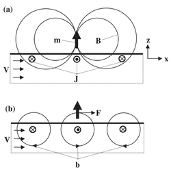
The analysis that leads to the scaling relation can be made quantitative by assuming that the magnet is a point dipole with dipole moment [math]\displaystyle{ \vec{m} = m \hat{e}_z }[/math] whose magnetic field is given by
where [math]\displaystyle{ \vec{R} = \vec{r} - L \hat{e} _z }[/math] and [math]\displaystyle{ R = \mid \vec{R} \mid }[/math]. Assuming a velocity field [math]\displaystyle{ \vec{v} = v \hat{e} _x }[/math] for [math]\displaystyle{ z \lt 0 }[/math], the eddy currents can be computed from Ohm's law for a moving electrically conducting fluid
subject to the boundary conditions [math]\displaystyle{ J_z=0 }[/math] at [math]\displaystyle{ z=0 }[/math] and [math]\displaystyle{ J_z \to 0 }[/math] as [math]\displaystyle{ z \to 1 }[/math]. First, the scalar electric potential is obtained as
from which the electric current density is readily calculated. They are indeed horizontal. Once they are known, the Biot–Savart law can be used to compute the secondary magnetic field [math]\displaystyle{ \vec{b} \left( \vec{r}\right) }[/math]. Finally, the force is given by
where the gradient of [math]\displaystyle{ \vec{b} }[/math] has to be evaluated at the location of the dipole. For the problem at hand all these steps can be carried out analytically without any approximation leading to the result
This provides us with the estimate
Conceptual setups
Lorentz force flowmeters are usually classified in several main conceptual setups. Some of them designed as static flowmeters where the magnet system is at rest and one measures the force acting on it. Alternatively, they can be designed as rotary flowmeters where the magnets are arranged on a rotating wheel and the spinning velocity is a measure of the flow velocity. Obviously, the force acting on a Lorentz force flowmeter depends both on the velocity distribution and on the shape of the magnet system. This classification depends on the relative direction of the magnetic field that is being applied respect to the direction of the flow. In Figure 3 one can distinguish diagrams of the longitudinal and the transverse Lorentz force flowmeters.
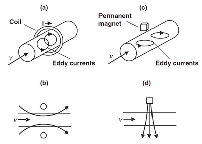
It is important to mention that even that in figures only a coil or a magnet are sketched, the principle holds for both.
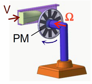
Rotary LFF consists of a freely rotating permanent magnet[9] (or an array of magnets mounted on a flywheel as shown in figure 4), which is magnetized perpendicularly to the axle it is mounted on. When such a system is placed close to a duct carrying an electrically conducting fluid flow, it rotates so that the driving torque due to the eddy currents induced by the flow is balanced by the braking torque induced by the rotation itself. The equilibrium rotation rate varies directly with the flow velocity and inversely with the distance between the magnet and the duct. In this case it is possible to measure either the torque on the magnet system or the angular velocity at which the wheel spins.
Practical applications
LFV is sought to be extended to all fluid or solid materials, providing that they are electrical conductors. As shown before, the Lorentz force generated by the flow depend linearly on the conductivity of the fluid. Typically, the electrical conductivity of molten metals is of the order of [math]\displaystyle{ 10^6 ~ S/m }[/math] so the Lorentz force is in the range of some mN. However, equally important liquids as glass melts and electrolytic solutions have a conductivity of [math]\displaystyle{ \sim ~ 1 ~ S/m }[/math] giving rise to a Lorentz force of the order of micronewtons or even smaller.
High Conducting media: liquid or solid metals
Among different possibilities to measure the effect on the magnet system, it has been successfully applied those based on the measurement of the deflection of a parallel spring under an applied force.[10] Firstly using a strain gauge and then recording the deflection of a quartz spring with an interferometer, in whose case the deformation is detected to within 0.1 nm.
Low Conducting media: Electrolytic solution or glass melts
Recent advance in LFV made it possible for metering flow velocity of media which has very low electroconductivity, particularly by varying parameters as well as using some state-of-art force measurement devices enable to measure flow velocity of electrolyte solutions with conductivity that is 106 times smaller than that for the liquid metals. There are variety of industrial and scientific applications where noncontact flow measurement through opaque walls or in opaque liquids is desirable. Such applications include flow metering of chemicals, food, beverages, blood, aqueous solutions in the pharmaceutical industry, molten salts in solar thermal power plants,[11] and high temperature reactors [12] as well as glass melts for high-precision optics.[13]
A noncontact flowmeter is a device that is neither in mechanical contact with the liquid nor with the wall of the pipe in which the liquid flows. Noncontact flowmeters are equally useful when walls are contaminated like in the processing of radioactive materials, when pipes are strongly vibrating or in cases when portable flowmeters are to be developed. If the liquid and the wall of the pipe are transparent and the liquid contains tracer particles, optical measurement techniques,[14][15] are effective enough tool to perform noncontact measurements. However, if either the wall or the liquid are opaque as is often the case in food production, chemical engineering, glass making, and metallurgy, very few possibilities for noncontact flow measurement exist.
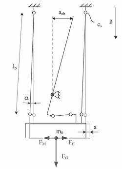
The force measurement system is an important part of the Lorentz force velocimetry. With high resolution force measurement system makes the measurement of even lower conductivity possible. Up to date has the force measurement system continually being developed. At first the pendulum-like setups was used (Figure 5). One of the experimental facilities consists of two high power (410 mT) magnets made of NdFeB suspended by thin wires on both side of channel thereby creating magnetic field perpendicular to the fluid flow, here deflection is measured by interferometer system,.[16][17] The second setup consists of state-of-art weighting balance system (Figure 6) from which is being hanged optimized magnets on the base of Halbach array system. While the total mass of both magnet systems are equal (1 kg), this system induces 3 times higher system response due to arrangement of individual elements in the array and its interaction with predefined fluid profile. Here use of very sensitive force measuring devices is desirable, since flow velocity is being converted from the very tiny detected Lorentz Force. This force in combination with unavoidable dead weight [math]\displaystyle{ F_G }[/math] of the magnet ([math]\displaystyle{ F_G = m\cdot g }[/math]) is around [math]\displaystyle{ F/F_G = 10^{-7} }[/math]. After that, the method of differential force measurement was developed. With this method two balance were used, one with magnet and the other is with same-weight-dummy. In this way the influence of environment would be reduced. Recently, it have been reported that the flow measurements by this method is possible for saltwater flows whose electrical conductivity is as small as 0.06 S/m (range of electrical conductivity of the regular water from tap).[18]
Lorentz force sigmometry
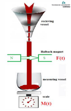
Lorentz force sigmometry (LOFOS)[19] is a contactless method for measuring the thermophysical properties of materials, no matter whether it is a fluid or a solid body. The precise measurements of electrical value, density, viscosity, thermal conductivity and surface tension of molten metals are in great importance in industry applications. One of the major problems in the experimental measurements of the thermophysical properties at high temperature (>1000 K) in the liquid state is the problem of chemical reaction between the hot fluid and the electrical probes. The basic equation for calculating the electrical conductivity is derived from the equation that links the mass flow rate [math]\displaystyle{ \dot{m} }[/math] and Lorentz force [math]\displaystyle{ F }[/math] generated by magnetic field in flow:
where [math]\displaystyle{ \Sigma = \frac{\sigma}{\rho} }[/math] is the specific electrical conductivity equals to the ratio of the electrical conductivity [math]\displaystyle{ \sigma }[/math] and the mass density of fluid [math]\displaystyle{ \rho }[/math]. [math]\displaystyle{ K }[/math] is a calibration factor that depends on the geometry of the LOFOS system.
From equation above the cumulative mass during operating time is determined as
where [math]\displaystyle{ \tilde{F} }[/math] is the integral of Lorentz force within the time process. From this equation and considering the specific electrical conductivity formula, one can derive the final equation to compute the electrical conductivity for the fluid, in the form
Time-of-flight Lorentz force velocimetry
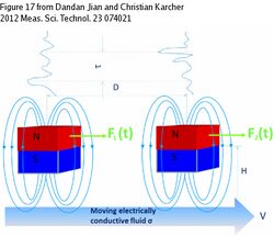
Time-of-flight Lorentz force velocimetry,[20][21] is intended for contactless determination of flow rate in conductive fluids. It can be successfully used even in case when such material properties as electrical conductivity or density are not precisely known under specific outer conditions. The last reason makes time-of-flight LFV especially important for industry application. According to time-of-flight LFV (Fig. 9) two coherent measurement systems are mounted on a channel one by one. The measurement is based on getting of cross-correlating function of signals, which are registered by two magnetic measurement's system. Every system consists of permanent magnet and force sensor, so inducing of Lorentz force and measurement of the reaction force are made simultaneously. Any cross-correlation function is useful only in case of qualitative difference between signals and for creating the difference in this case turbulent fluctuations are used. Before reaching of measurement zone of a channel liquid passes artificial vortex generator that induces strong disturbances in it. And when such fluctuation-vortex reaches magnetic field of measurement system we can observe a peak on its force-time characteristic while second system still measures stable flow. Then according to the time between peaks and the distance between measurement system observer can estimate mean velocity and, hence, flow rate of the liquid by equation:
where [math]\displaystyle{ D }[/math] is the distance between magnet system, [math]\displaystyle{ \tau }[/math] the time delay between recorded peaks, and [math]\displaystyle{ k }[/math] is obtained experimentally for every specific liquid, as shown in figure 9.
Lorentz force eddy current testing

A different, albeit physically closely related challenge is the detection of deeply lying flaws and inhomogeneities in electrically conducting solid materials.
In the traditional version of eddy current testing an alternating (AC) magnetic field is used to induce eddy currents inside the material to be investigated. If the material contains a crack or flaw which make the spatial distribution of the electrical conductivity nonuniform, the path of the eddy currents is perturbed and the impedance of the coil which generates the AC magnetic field is modified. By measuring the impedance of this coil, a crack can hence be detected. Since the eddy currents are generated by an AC magnetic field, their penetration into the subsurface region of the material is limited by the skin effect. The applicability of the traditional version of eddy current testing is therefore limited to the analysis of the immediate vicinity of the surface of a material, usually of the order of one millimeter. Attempts to overcome this fundamental limitation using low frequency coils and superconducting magnetic field sensors have not led to widespread applications.
A recent technique, referred to as Lorentz force eddy current testing (LET),[22][23] exploits the advantages of applying DC magnetic fields and relative motion providing deep and relatively fast testing of electrically conducting materials. In principle, LET represents a modification of the traditional eddy current testing from which it differs in two aspects, namely (i) how eddy currents are induced and (ii) how their perturbation is detected. In LET eddy currents are generated by providing the relative motion between the conductor under test and a permanent magnet (see figure 10). If the magnet is passing by a defect, the Lorentz force acting on it shows a distortion whose detection is the key for the LET working principle. If the object is free of defects, the resulting Lorentz force remains constant.
Advantages & Limitations
The advantages of LFV are
- LFV is a non-contact techniques of flow rate measurement.
- LFV can be successfully applied for aggressive and high-temperature fluids like liquid metals.
- Mean flow rate or mean velocity of fluid can be obtained without depending on flow's inhomogeneities and zones of turbulence.
The limitations of the LFV are
- Necessity of temperature control of measurement system because of strong dependence of magnet's magnetic field on temperature. High temperature could cause irretrievable loss of the magnetic properties of permanent magnet (Curie temperature).
- Restriction of measurement zone by permanent magnet's dimensions.
- Necessity of liquid level's control in case of work with open channel.
- Rapid decay of the magnetic fields give rise to tiny forces on the magnet system.
See also
External links
References
- ↑ 1.0 1.1 1.2 Thess, A.; Votyakov, E. V.; Kolesnikov, Y. (2006-04-25). "Lorentz Force Velocimetry". Physical Review Letters (American Physical Society (APS)) 96 (16): 164601. doi:10.1103/physrevlett.96.164501. ISSN 0031-9007. PMID 16712237.
- ↑ Arthur J. Shercliff: Theory of Electromagnetic Flow Measurement. Cambridge University Press, ISBN:978-0-521-33554-6.
- ↑ Kolesnikov, Yurii; Karcher, Christian; Thess, André (2011-02-24). "Lorentz Force Flowmeter for Liquid Aluminum: Laboratory Experiments and Plant Tests". Metallurgical and Materials Transactions B (Springer Science and Business Media LLC) 42 (3): 441–450. doi:10.1007/s11663-011-9477-6. ISSN 1073-5615.
- ↑ 4.0 4.1 "Research Training Group LORENTZ FORCE". http://www.tu-ilmenau.de/lorentz-force/.
- ↑ Priede, Jānis; Buchenau, Dominique; Gerbeth, Gunter (2011-04-08). "Contactless electromagnetic phase-shift flowmeter for liquid metals". Measurement Science and Technology 22 (5): 055402. doi:10.1088/0957-0233/22/5/055402. ISSN 0957-0233.
- ↑ 6.0 6.1 Thess, André; Votyakov, Evgeny; Knaepen, Bernard; Zikanov, Oleg (2007-08-31). "Theory of the Lorentz force flowmeter". New Journal of Physics (IOP Publishing) 9 (8): 299. doi:10.1088/1367-2630/9/8/299. ISSN 1367-2630.
- ↑ Baumgartl, J.; Hubert, A.; Müller, G. (1993). "The use of magnetohydrodynamic effects to investigate fluid flow in electrically conducting melts". Physics of Fluids A: Fluid Dynamics (AIP Publishing) 5 (12): 3280–3289. doi:10.1063/1.858685. ISSN 0899-8213.
- ↑ Stefani, Frank; Gundrum, Thomas; Gerbeth, Gunter (2004-11-16). "Contactless inductive flow tomography". Physical Review E 70 (5): 056306. doi:10.1103/physreve.70.056306. ISSN 1539-3755. PMID 15600752.
- ↑ Priede, Jānis; Buchenau, Dominique; Gerbeth, Gunter (2011). "Single-magnet rotary flowmeter for liquid metals". Journal of Applied Physics 110 (3): 034512. doi:10.1063/1.3610440. ISSN 0021-8979.
- ↑ Heinicke, Christiane; Tympel, Saskia; Pulugundla, Gautam; Rahneberg, Ilko; Boeck, Thomas; Thess, André (2012-12-15). "Interaction of a small permanent magnet with a liquid metal duct flow". Journal of Applied Physics (AIP Publishing) 112 (12): 124914. doi:10.1063/1.4770155. ISSN 0021-8979.
- ↑ Herrmann, Ulf; Kelly, Bruce; Price, Henry (2004). "Two-tank molten salt storage for parabolic trough solar power plants". Energy (Elsevier BV) 29 (5–6): 883–893. doi:10.1016/s0360-5442(03)00193-2. ISSN 0360-5442.
- ↑ Forsberg, Charles W.; Peterson, Per F.; Pickard, Paul S. (2003). "Molten-Salt-Cooled Advanced High-Temperature Reactor for Production of Hydrogen and Electricity". Nuclear Technology (Informa UK Limited) 144 (3): 289–302. doi:10.13182/nt03-1. ISSN 0029-5450.
- ↑ U. Lange and H. Loch, "Instabilities and stabilization of glass pipe flow" in Mathematical Simulation in Glass Technology, Schott Series on Glass and Glass Ceramics, edited by D. Krause and H. Loch (Springer Verlag, 2002)
- ↑ C. Tropea, A. L. Yarin, and J. F. Foss, Handbook of Experimental Fluid Mechanics, Springer-Verlag, GmbH, 2007
- ↑ F. Durst, A. Melling, and J. H. Whitelaw, Principles and Practice of Laser-Doppler Anemometry, 2nd ed. Academic, London, 1981
- ↑ Wegfrass, André; Diethold, Christian; Werner, Michael; Resagk, Christian; Fröhlich, Thomas; Halbedel, Bernd; Thess, André (2012-08-24). "Flow rate measurement of weakly conducting fluids using Lorentz force velocimetry". Measurement Science and Technology (IOP Publishing) 23 (10): 105307. doi:10.1088/0957-0233/23/10/105307. ISSN 0957-0233.
- ↑ 17.0 17.1 Diethold, Christian; Hilbrunner, Falko (2012-06-11). "Force measurement of low forces in combination with high dead loads by the use of electromagnetic force compensation". Measurement Science and Technology (IOP Publishing) 23 (7): 074017. doi:10.1088/0957-0233/23/7/074017. ISSN 0957-0233.
- ↑ Vasilyan, Suren (2015). "Towards metering tap water by Lorentz Force Velocimetry". Measurement Science and Technology 26 (11): 115302. doi:10.1088/0957-0233/26/11/115302. Bibcode: 2015MeScT..26k5302V. http://iop.com.
- ↑ Uhlig, Robert P.; Zec, Mladen; Ziolkowski, Marek; Brauer, Hartmut; Thess, André (2012). "Lorentz force sigmometry: A contactless method for electrical conductivity measurements". Journal of Applied Physics (AIP Publishing) 111 (9): 094914. doi:10.1063/1.4716005. ISSN 0021-8979.
- ↑ 20.0 20.1 Jian, Dandan; Karcher, Christian (2012-06-11). "Electromagnetic flow measurements in liquid metals using time-of-flight Lorentz force velocimetry". Measurement Science and Technology (IOP Publishing) 23 (7): 074021. doi:10.1088/0957-0233/23/7/074021. ISSN 0957-0233.
- ↑ Viré, Axelle; Knaepen, Bernard; Thess, André (2010). "Lorentz force velocimetry based on time-of-flight measurements". Physics of Fluids (AIP Publishing) 22 (12): 125101. doi:10.1063/1.3517294. ISSN 1070-6631.
- ↑ 22.0 22.1 M. Zec et al., Fast Technique for Lorentz Force Calculations in Nondestructive Testing Applications, COMPUMAG 2013, Budapest, Hungary
- ↑ Uhlig, Robert P.; Zec, Mladen; Brauer, Hartmut; Thess, André (2012-07-24). "Lorentz Force Eddy Current Testing: a Prototype Model". Journal of Nondestructive Evaluation (Springer Science and Business Media LLC) 31 (4): 357–372. doi:10.1007/s10921-012-0147-7. ISSN 0195-9298.
 |
