Physics:Loudspeaker measurement

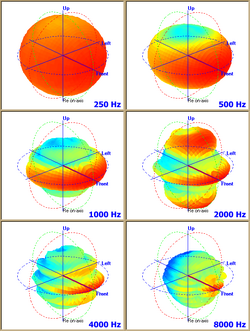
Loudspeaker measurement is the practice of determining the behaviour of loudspeakers by measuring various aspects of performance. This measurement is especially important because loudspeakers, being transducers, have a higher level of distortion than other audio system components used in playback or sound reinforcement.
Anechoic measurement

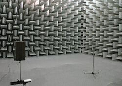
One way to test a loudspeaker requires an anechoic chamber, with an acoustically transparent floor-grid. The measuring microphone is normally mounted on an unobtrusive boom (to avoid reflections) and positioned 1 metre in front of the drive units on the axis with the high-frequency driver. While this can produce repeatable results, such a 'free-space' measurement is not representative of performance in a room, especially a small room. For valid results at low frequencies, a very large anechoic chamber is needed, with large absorbent wedges on all sides. Most anechoic chambers are not designed for accurate measurement down to 20 Hz and most are not capable of measuring below 80 Hz.
Tetrahedral chamber

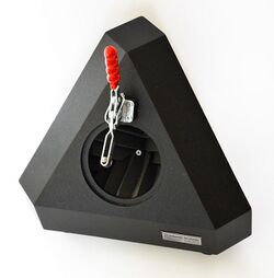
A tetrahedral chamber is capable of measuring the low frequency limit of the driver without the large footprint required by an anechoic chamber. This compact measurement system for loudspeaker drivers is defined in IEC 60268-21:2018,[1] IEC 60268-22:2020[2] and AES73id-2019.[3]
Half-space measurement
An alternative is to simply lay the speaker on its back pointing at the sky on open grass. Ground reflection will still interfere but will be greatly reduced in the mid-range because most speakers are directional, and only radiate very low frequencies backward. Putting absorbent material around the speaker will reduce mid-range ripple by absorbing rear radiation. At low frequencies, the ground reflection is always in-phase, so that the measured response will have increased bass, but this is what generally happens in a room anyway, where the rear wall and the floor both provide a similar effect. There is a good case, therefore, using such half-space measurements, and aiming for a flat half-space response. Speakers that are equalised to give a flat free-space response, will always sound very bass-heavy indoors, which is why monitor speakers tend to incorporate half-space, and quarter-space (for corner use) settings which bring in attenuation below about 400 Hz.
Digging a hole and burying the speaker flush with the ground allows far more accurate half-space measurement, creating the loudspeaker equivalent of the boundary effect microphone (all reflections precisely in-phase) but any rear port must remain unblocked, and any rear-mounted amplifier must be allowed cooling air. Diffraction from the edges of the enclosure is reduced, creating a repeatable and accurate, but not very representative, response curve.
Room measurements
At low frequencies, most rooms have resonances at a series of frequencies where a room dimension corresponds to a multiple of half wavelengths. Sound travels at about 1,100 feet per second (340 m/s), so a room 20 feet (6.1 m) long will have resonances from 27.5 Hz upwards. These resonant modes cause large peaks and dips in the sound level of a constant signal as the frequency of that signal varies from low to high.
Additionally, reflections, dispersion, absorption, etc. all strongly alter the perceived sound, though this is not necessarily consciously noticeable for either music or speech, at frequencies above those dominated by room modes. These alterations depend on speaker locations with respect to reflecting, dispersing, or absorbing surfaces (including changes in speaker orientation) and on the listening position. In unfortunate situations, a slight movement of any of these, or of the listener, can cause considerable differences. Complex effects, such as stereo (or multiple channel) aural integration into a unified perceived "sound stage" can be lost easily.
There is limited understanding of how the ear and brain process sound to produce such perceptions, and so no measurement, or combination of measurements, can assure successful perceptions of, for instance, the "sound stage" effect. Thus, there is no assured procedure that will maximize speaker performance in any listening space (with the exception of the sonically unpleasant anechoic chamber). Some parameters, such as reverberation time (in any case, really applicable only to larger volumes), and overall room "frequency response" can be somewhat adjusted by addition or subtraction of reflecting, diffusing, or absorbing elements, but, though this can be remarkably effective (with the right additions or subtractions and placements), it remains something of an art and a matter of experience. In some cases, no such combination of modifications has been found to be very successful.
Microphone positioning
All multi-driver speakers (unless they are coaxial) are difficult to measure correctly if the measuring microphone is placed close to the loudspeaker and slightly above or below the optimum axis because the different path length from two drivers producing the same frequency leads to phase cancellation. It is useful to remember that, as a rule of thumb, 1 kHz has a wavelength of 1 ft (0.30 m) in air, and 10 kHz a wavelength of only 1-inch (25 mm). Published results are often only valid for very precise positioning of the microphone to within a centimetre or two.
Measurements made at 2 or 3 m, in the actual listening position between two speakers can reveal something of what is actually going on in a listening room. Horrendous though the resulting curve generally appears to be (in comparison to other equipment), it provides a basis for experimentation with absorbent panels. Driving both speakers is recommended, as this stimulates low-frequency room 'modes' in a representative fashion. This means the microphone must be positioned precisely equidistant from the two speakers if 'comb-filter' effects (alternate peaks and dips in the measured room response at that point) are to be avoided. Positioning is best done by moving the mic from side to side for maximum response on a 1 kHz tone, then a 3 kHz tone, then a 10 kHz tone. While the very best modern speakers can produce a frequency response flat to ±1 dB from 40 Hz to 20 kHz in anechoic conditions, measurements at 2 m in a real listening room are generally considered good if they are within ±12 dB.
Nearfield measurements
Room acoustics have a much smaller effect on nearfield measurements, so these can be appropriate when anechoic chamber analysis cannot be done. Measurements should be done at much shorter distances from the speaker than the speaker (or the sound source, like horn, vent) overall diameter, where the half-wavelength of the sound is smaller than the speaker overall diameter. These measurements yield direct speaker efficiency, or the average sensitivity, without directional information. For a multiple sound source speaker system, the measurement should be carried out for all sound sources (woofer, bass-reflex vent, midrange speaker, tweeter...). These measurements are easy to carry out, can be done at almost any room, more punctual than in-box measurements, and predicts half-space measurements, but without directivity information.[4]
Frequency response measurement
Frequency response measurements are only meaningful if shown as a graph, or specified in terms of ±3 dB limits (or other limits). A weakness of most quoted figures is a failure to state the maximum SPL available, especially at low frequencies. A power bandwidth measurement is, therefore, most useful, in addition to frequency response, this being a plot of maximum SPL out for a given distortion figure across the audible frequency range.
Distortion measurement
Distortion measurements on loudspeakers can only go as low as the distortion of the measurement microphone itself of course, at the level tested. The microphone should ideally have a clipping level of 120 to 140 dB SPL if high-level distortion is to be measured. A typical top-end speaker, driven by a typical 100watt power amplifier, cannot produce peak levels much above 105 dB SPL at 1 m (which translates roughly to 105 dB at the listening position from a pair of speakers in a typical listening room). Achieving truly realistic reproduction requires speakers capable of much higher levels than this, ideally around 130 dB SPL. Even though the level of live music measured on a (slow responding and RMS reading) sound level meter might be in the region of 100 dB SPL, programme level peaks on percussion will far exceed this. Most speakers give around 3% distortion measured 468-weighted 'distortion residue' reducing slightly at low levels. Electrostatic speakers can have lower harmonic distortion but suffer higher intermodulation distortion. 3% distortion residue corresponds to 1 or 2% total harmonic distortion. Professional monitors may maintain modest distortion up to around 110 dB SPL at 1 m, but almost all domestic speaker systems distort badly above 100 dB SPL.
Colouration analysis
Loudspeakers differ from most other items of audio equipment in suffering from colouration, the tendency of various parts of the speaker — the cone, its surround, the cabinet, the enclosed space — to carry on moving when the signal ceases. All forms of resonance cause this, by storing energy, and resonances with high Q factor are especially audible. Much of the work that has gone into improving speakers in recent years has been about reducing colouration, and Fast Fourier Transform, or FFT, measuring equipment was introduced in order to measure the delayed output from speakers and display it as a time vs. frequency waterfall plot or spectrogram plot. Initially, an analysis was performed using impulse response testing, but this 'spike' suffers from having very low energy content if the stimulus is to remain within the peak ability of the speaker. Later equipment uses correlation on other stimulus such as a maximum length sequence system analyser (MLSSA).[5] Using multiple sine wave tones as a stimulus signal and analyzing the resultant output, Spectral Contamination testing provides a measure of a loudspeakers 'self-noise' distortion component. This 'picket fence' type of signal can be optimized for any frequency range, and the results correlate exceptionally well with sound quality listening tests.
See also
- Audio power
- Audio noise measurement
- Audio quality measurement
- Bandwidth extension
- Directional sound
- Isobaric loudspeaker
- Loudspeaker acoustics
- Parabolic loudspeaker
- Programme levels
- Speaker driver
- Spherical coordinate system
- Studio monitor
References
- ↑ IEC 60268-21:2018 https://webstore.iec.ch/publication/28687
- ↑ IEC 60268-22:2020 https://webstore.iec.ch/publication/60560
- ↑ AES73id-2019 https://www.aes.org/publications/standards/search.cfm?docID=109
- ↑ D B Keele, Jr: Low-Frequency Loudspeaker Assessment by Nearfield Sound-Pressure Measurement, JAES Volume 22 Issue 3 pp. 154-162; April 1974;https://www.aes.org/e-lib/browse.cfm?elib=2774
- ↑ MLSSA site
External links
- MLSSA site
- Praxis loudspeaker measurement system
- CONEQ loudspeaker measurement and correction system
- TTC Tetrahedral Test Chambers
- Audio & Loudspeaker Technologies International (ALTI)
 |

