Physics:Momentum–depth relationship in a rectangular channel
In classical physics, momentum is the product of mass and velocity and is a vector quantity, but in fluid mechanics it is treated as a longitudinal quantity (i.e. one dimension) evaluated in the direction of flow. Additionally, it is evaluated as momentum per unit time, corresponding to the product of mass flow rate and velocity, and therefore it has units of force. The momentum forces considered in open channel flow are dynamic force – dependent of depth and flow rate – and static force – dependent of depth – both affected by gravity. The principle of conservation of momentum in open channel flow is applied in terms of specific force, or the momentum function; which has units of length cubed for any cross sectional shape, or can be treated as length squared in the case of rectangular channels. Although not being technically correct, the term momentum will be used to replace the concept of the momentum function. The conjugate depth equation, which describes the depths on either side of a hydraulic jump, can be derived from the conservation of momentum in rectangular channels, based upon the relationship between momentum and depth of flow. The concept of momentum can also be applied to evaluate the thrust force on a sluice gate, a device that conserves specific energy but loses momentum.
Derivation of the momentum function equation from momentum–force balance
In fluid dynamics, the momentum-force balance over a control volume is given by:
- [math]\displaystyle{ M_1 + M_2 = F_w + F_f + F_{P1} + F_{P2} }[/math]
Where:
- M = momentum per unit time (ML/t2)
- Fw = gravitational force due to weight of water (ML/t2)
- Ff = force due to friction (ML/t2)
- FP = pressure force (ML/t2)
- subscripts 1 and 2 represent upstream and downstream locations, respectively
- Units: L = length, t = time, M = mass
Applying the momentum-force balance in the direction of flow, in a horizontal channel (i.e. Fw = 0) and neglecting the frictional force (smooth channel bed and walls):
- [math]\displaystyle{ M_{1x} + M_{2x} = F_{P1x} + F_{P2x} }[/math]
Substituting the components of momentum per unit time and pressure force (with their respective positive or negative directions):
- [math]\displaystyle{ M_{1x} = \dot{m}V_{1x} = - \rho QV_1 \quad and \quad F_{P1x} = \overline{P}_1A_1 }[/math]
- [math]\displaystyle{ M_{2x} = \dot{m}V_{2x} = - \rho QV_2 \quad and \quad F_{P2x} = \overline{P}_2A_2 }[/math]
The equation becomes:
- [math]\displaystyle{ -\rho QV_1 + \rho QV_2 = \overline{P}_1A_1 - \overline{P}_2A_2 }[/math]
Where:
- [math]\displaystyle{ \dot{m} }[/math] = mass flow rate (M/t)
- ρ = fluid density (M/L3)
- Q = flow rate or discharge in the channel (L3/t)
- V = flow velocity (L/t)
- [math]\displaystyle{ \overline{P} }[/math] = average pressure (M/Lt2)
- A = cross sectional area of flow (L2)
- subscripts 1 and 2 represent upstream and downstream locations, respectively
- Units: L (length); t (time); M (mass)
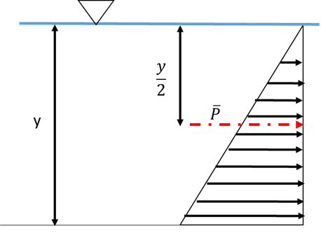
The hydrostatic pressure distribution has a triangular shape from the water surface to the bottom of the channel (Figure 1). The average pressure can be obtained from the integral of the pressure distribution:
- [math]\displaystyle{ \overline{P} = {1 \over 2} \rho gy }[/math]
Where:
- y = flow depth (L)
- g = gravitational constant (L/t2)
Applying the continuity equation:
- [math]\displaystyle{ Q = V_1A_1 = V_2A_2 }[/math]
For the case of rectangular channels (i.e. constant width “b”) the flow rate, Q, can be replaced by the unit discharge q, where q = Q/b, which yields:
- [math]\displaystyle{ q = V_1y_1 = V_2y_2 }[/math]
And therefore:
- [math]\displaystyle{ V_1 = q/y_1 \quad and \quad V_2 = q/y_2 }[/math]
By dividing the left and right side of the momentum-force equation by the channel’s width, and substituting the above relationships:
- [math]\displaystyle{ -{\rho q \left({q \over {y_1}}\right)} + {\rho q \left({q \over {y_2}}\right)} = \left({1 \over 2} \rho g{y_1} \right) {y_1} -{\left({1 \over 2} \rho g{y_2} \right) {y_2}} }[/math]
- subscripts 1 and 2 represent upstream and downstream locations, respectively.
Dividing through by ρg:
- [math]\displaystyle{ -{{q^2 \over g{y_1}}} + {q^2 \over g{y_2}} = {{y_1} ^2 \over 2}-{{y_2} ^2 \over 2} }[/math]
Separating the variables based on the sides of the jump:
- [math]\displaystyle{ {{y_1} ^2 \over 2}+{q^2 \over g{y_1}} = {{y_2} ^2 \over 2}+{q^2 \over g{y_2}} }[/math]
In the above relationship both sides correspond to the specific force, or momentum function per channel width, also called Munit.
- [math]\displaystyle{ M_\text{unit} = {y^2 \over 2}+{q^2 \over gy} }[/math]
This equation is only valid in certain unique circumstances, such as in a laboratory flume, where the channel is truly rectangular and the channel slope is zero or small. When this is the case, it is possible to assume that a hydrostatic pressure distribution applies. Munit is expressed in units of L2. If the channel width is known, the full specific force (L3) at a point can be determined by multiplying Munit by the width, b.
Hydraulic jumps and conservation of momentum
Figure 2 depicts a hydraulic jump. A hydraulic jump is a region of rapidly varied flow and is formed in a channel when a supercritical flow transitions into a subcritical flow.[1] This change in flow type is manifested as an abrupt change in the flow depth from the shallower, faster-moving supercritical flow to the deeper, slower-moving subcritical flow. Assuming no additional drag forces, momentum is conserved.
A jump causes the water surface to rise abruptly, and as a result, surface rollers are formed, intense mixing occurs, air is entrained, and usually a large amount of energy is dissipated. For these reasons, in engineered systems a hydraulic jump is sometimes forced in an attempt to dissipate flow energy, to mix chemicals, or to act as an aeration device.[2][3]
The law of conservation of momentum states that the total momentum of a closed system of objects (which has no interactions with external agents) is constant.[4] Despite the fact that there is an energy loss, momentum across a hydraulic jump is still conserved. This means that the flow depth on either side of the jump will have the same momentum, and in this way, if the momentum and flow depth on either side of the jump is known, it is possible to determine the depth on the other side of the jump. These paired depths are known as sequent depths, or conjugate depths. The latter is valid unless the jump is caused by an external force or outside influence.
The green box in Figure 2 represents the control volume enclosing the jump system and shows the major pressure forces on the system (FP1 and FP2). As this system is considered to be horizontal (or nearly horizontal) and frictionless, the horizontal components of force that normally exist due to friction (Ff) and the weight of water from a sloping channel (Fw) are neglected. It is worth to noting that the slope of the triangular hydrostatic pressure distributions on each location corresponds to the specific weight of water (γ), which has units of (m/L2t2)
The M-y diagram
An M-y diagram is a plot of the depth of flow (y) versus momentum (M). In this case M does not refer to momentum (M/Lt2), but to the momentum function (L3 or L2). This produces a specific momentum curve that is generated by calculating momentum for a range of depth values and graphing the results. Each M-y curve is unique for a specific flowrate, Q, or unit discharge, q. The momentum on the x-axis of the plot can either have units of length3 (when using the general momentum function equation) or units of length2 (when using the rectangular form Munit equation). In a rectangular channel of unit width, an M-y curve is plotted using:
- [math]\displaystyle{ M_\text{unit} = {q^2 \over gy} + {y^2 \over 2} }[/math]
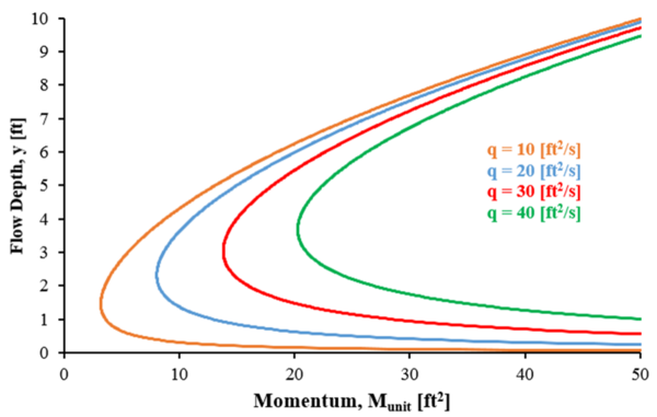
Figure 3 depicts a sample M-y diagram showing the plots of four specific momentum curves. Each of these curves correspond to a specific q as noted in the figure. As unit discharge increases, the curve shifts to the right.
M-y diagrams can provide information about the characteristics and behavior of a certain discharge in a channel. Primarily, an M-y diagram will show which flow depths correspond to supercritical or subcritical flow for a given discharge, as well as defining the critical depth and critical momentum of a flow. In addition, M-y diagrams can aid in finding conjugate depths of flow that have the same specific force or momentum function, as in the case of flow depths on either side of a hydraulic jump. A dimensionless form of the M-y diagram representing any unit discharge can be created and utilized in place of the particular M-y curves discussed here and referred to in Figure 3.
Critical flow
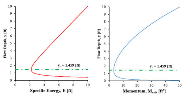
A flow is termed critical if the bulk velocity of the flow [math]\displaystyle{ V }[/math] is equal to the propagation velocity of a shallow gravity wave [math]\displaystyle{ \sqrt {gy} }[/math].[1][5] At critical flow, the specific energy and the specific momentum (force) are at a minimum for a given discharge.[1] Figure 4 shows this relationship by showing a specific energy curve (E-y diagram) side-by-side to its corresponding specific momentum curve (M-y diagram) for a unit discharge q = 10 ft2/s. The green line on these figures intersects the curves at the minimum x-axis value that each curve exhibits. As noted, both of these intersections occur at a depth of approximately 1.46 ft, which is the critical flow depth for the specific conditions in the given channel. This critical depth represents the transition depth in the channel where the flow switches from supercritical flow to subcritical flow or vice versa.
In a rectangular channel, critical depth (yc) can also be found mathematically using the following equation:
- [math]\displaystyle{ y_c = \left({q^2 \over g} \right)^{1 \over 3} }[/math]
Where:
- g = gravitational constant (L/t2)
- q = unit flowrate or discharge – for a rectangular channel, discharge per unit channel width (L2/t)
Supercritical flow versus subcritical flow on an M-y diagram
As mentioned before, an M-y diagram can provide an indication of flow classification for a given depth and discharge. When flow is not critical it is classified as either subcritical or supercritical. This distinction is based on the Froude number of the flow, which is the ratio of the bulk velocity (V) to the propagation velocity of a shallow wave :[math]\displaystyle{ \left({\sqrt {gy}}\right) }[/math].[5] The generic equation of the Froude number is expressed in terms of gravity (g), the flow’s velocity (V) and the hydraulic depth (A/B), where (A) represents the cross sectional area and (B) the top width. For rectangular channels, this ratio is equal to the depth of flow (y).
- [math]\displaystyle{ F_r={{V}\over {\sqrt{g \left({A \over B} \right)}}}={{V}\over {\sqrt {gy}}} }[/math]
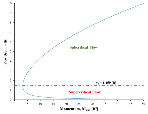
A Froude number greater than one is supercritical, and a Froude number less than one is subcritical. In general, supercritical flows are shallow and fast and subcritical flows are deep and slow. These different flow classifications are also represented on M-y diagrams where different regions of the graph represent different flow types. Figure 5 shows these regions, with a specific momentum curve corresponding to a q = 10 ft2/s. As stated previously, critical flow is represented by the minimum momentum that exists on the curve (green line). Supercritical flows correspond to any point on the momentum curve that has a depth less than the critical depth with subcritical flows having a depth greater than critical depth.[6]
Conjugate depths in a rectangular channel
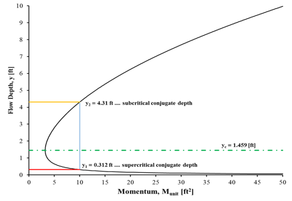
Conjugate, or sequent, depths are the paired depths that result upstream and downstream of a hydraulic jump, with the upstream flow being supercritical and downstream flow being subcritical. Conjugate depths can be found either graphically using a specific momentum curve or algebraically with a set of equations. Because momentum is conserved over a hydraulic jump conjugate depths have equivalent momentum, and given a discharge, the conjugate to any flow depth can be determined with an M-y diagram (Figure 6).
A vertical line that crosses the M-y curve twice (i.e. non-critical flow conditions) represents the depths on opposite sides of a hydraulic jump. Given sufficient momentum (momentum greater than critical flow), a conjugate depth pair exists at each point where the vertical line intersects the M-y curve. Figure 6 exemplifies this behavior with a momentum of 10 ft2 for a unit discharge of 10 ft2/s. This momentum line crosses the M-y curve at depths of 0.312 (y1) and 4.31 feet (y2). Depth y1 corresponds to the supercritical depth upstream of the jump and depth y2 corresponds to the subcritical depth downstream of the jump.
Conjugate depths can also be calculated using the Froude number and depth of either the supercritical or subcritical flow. The following equations can be used to determine the conjugate depth to a known depth in a rectangular channel:
- [math]\displaystyle{ y_2 = {y_1 \over 2} \left(-1 + \sqrt{(1 + 8{F_{r_1}}^2)}\right) \quad or \quad y_1 = {y_2 \over 2} \left(-1 + \sqrt{(1 + 8{F_{r_2}}^2)} \right) }[/math]
Derivation of conjugate depth equation for a rectangular channel
Start with the conservation of momentum function [math]\displaystyle{ M_1 = M_2 }[/math], for rectangular channels:
- [math]\displaystyle{ \left({q^2 \over gy_1} + {y_1^2 \over 2} \right) = \left({q^2 \over gy_2} + {y_2^2 \over 2}\right) }[/math]
Where:
- q = discharge per unit channel width (L2/t)
- g = gravitational constant (L/t2)
- y = flow depth (L)
- subscripts 1 and 2 represent upstream and downstream locations, respectively.
Isolate the q2 terms on one side of the equal sign with the [math]\displaystyle{ y^2 }[/math] terms on the other side:
- [math]\displaystyle{ {q^2 \over gy_1} - {q^2 \over gy_2} = -{y_1^2 \over 2} + {y_2^2 \over 2} }[/math]
Factor the constant terms q2/g and 1/2:
- [math]\displaystyle{ {q^2 \over g} \left({1 \over y_1} - {1 \over y_2}\right) = {1 \over 2} ({y_2^2} - {y_1^2}) }[/math]
Combine the depth terms on the left side and expand the quadratic on the right side:
- [math]\displaystyle{ {q^2 \over g} \left({{y_2 - y_1} \over {y_1y_2}} \right) = {1 \over 2} ({y_2 - y_1})({y_2 + y_1}) }[/math]
Divide by [math]\displaystyle{ (y_2 - y_1) }[/math]:
- [math]\displaystyle{ {q^2 \over g} \left({1 \over {y_1y_2}} \right) = {1 \over 2}({y_2 + y_1}) }[/math]
Recall from continuity in a rectangular channel that:
- [math]\displaystyle{ q = V_1y_1 = V_2y_2 }[/math]
Substitute [math]\displaystyle{ V_1y_1 }[/math] into the left side of the equation for q:
- [math]\displaystyle{ {{V_1^2y_1^2} \over {gy_1y_2}} = {{V_1^2y_1} \over {gy_2}} = {{y_2 + y_1} \over 2} }[/math]
Divide by [math]\displaystyle{ {y_1/y_2} }[/math]:
- [math]\displaystyle{ {{V_1^2} \over {g}} = {{y_2({y_2 + y_1})} \over {2y_1}} }[/math]
Divide by [math]\displaystyle{ y_1 }[/math] and recognize that the left hand side is now equal to Fr12:
- [math]\displaystyle{ {{V_1^2} \over {gy_1}} = {{y_2({y_2 + y_1})} \over {2y_1^2}} \Rightarrow {V_1^2 \over gy_1} = F_{r_1}^2 = {y_2^2 \over {2y_1^2}} + {{y_2y_1} \over 2y_1^2} = {y_2^2 \over {2y_1^2}} + {{y_2} \over 2y_1} }[/math]
Rearrange and set the equation equal to zero:
- [math]\displaystyle{ 0 = {y_2^2 \over {2y_1^2}} + {{y_2} \over 2y_1} - F_{r_1}^2 }[/math]
To facilitate the next step, let [math]\displaystyle{ x = {y_2/y_1} }[/math], and the above equation becomes:
- [math]\displaystyle{ 0 = {1 \over {2}}x^2 + {1 \over {2}}x - F_{r_1}^2 }[/math]
Solve for [math]\displaystyle{ x }[/math] using the quadratic equation with [math]\displaystyle{ a = {1/2} }[/math], [math]\displaystyle{ b = {1/2} }[/math], and [math]\displaystyle{ c = }[/math]-Fr12:
- [math]\displaystyle{ x=\frac{-b \pm \sqrt {b^2-4ac}}{2a} \quad \Rightarrow \quad x = {y_2 \over y_1} = \frac{-{1 \over 2} \pm \sqrt {{1 \over 2}^2-4\left({1 \over 2}\right)\left(-F_{r_1}^2\right)}}{2\left({1 \over 2}\right)} = \frac{-{1 \over 2} \pm \sqrt {{1 \over 4}+2{F_{r_1}^2}}}{1} }[/math]
Pull out the 1/4 inside of the square root:
- [math]\displaystyle{ {y_2 \over y_1} = -{1 \over 2} \pm \sqrt {{1 \over 4} \left(1+8{F_{r_1}^2}\right)} = -{1 \over 2} \pm {1 \over 2} \sqrt {\left(1+8{F_{r_1}^2}\right)} }[/math]
Focus on the root with the positive second term:
- [math]\displaystyle{ {y_2 \over y_1} = -{1 \over 2} + {1 \over 2} \sqrt {\left(1+8{F_{r_1}^2}\right)} \quad \Rightarrow \quad y_2 = -{y_1 \over 2} + {y_1 \over 2} \sqrt {\left(1+8{F_{r_1}^2}\right)} }[/math]
Factor the (y1/2) terms:
- [math]\displaystyle{ y_2 = {y_1 \over 2} \left(-1 + \sqrt {\left(1+8{F_{r_1}^2}\right)}\right) }[/math]
The above is the conjugate depth equation in a rectangular channel and can be used to find the subcritical or supercritical depth from known conditions, either upstream (y1, Fr1) or downstream (y2, Fr2).
A note on conjugate depths versus alternative depths
It is important not to confuse conjugate depths (between which momentum is conserved) with alternate depths (between which energy is conserved). In the case of a hydraulic jump, the flow experiences a certain amount of energy headloss so that the subcritical flow downstream of the jump contains less energy than the supercritical flow upstream of the jump. Alternate depths are valid over energy conserving devices such as sluice gates and conjugate depths are valid over momentum conserving devices such as hydraulic jumps.
Application of the momentum function equation to evaluate the thrust force on a sluice gate
The momentum equation can be applied to determine the force exerted by water on a sluice gate (Figure 7). Contrary to the conservation of fluid energy when a flow encounters a sluice gate, the momentum upstream and downstream of the gate is not conserved. The thrust force exerted by water on a gate placed in a rectangular channel can be obtained from the following equation, which can be derived in the same way as the conservation of momentum equation for rectangular channels:
- [math]\displaystyle{ F_\text{thrust-gate} = \gamma b(\Delta M) = \gamma b(M_\text{unit,1} - M_\text{unit,2}) }[/math]
Where:
- Fthrust-gate = force exerted by water on the sluice gate (ML/t2)
- γ = specific weight of water (M/L2t2)
- ΔMunit = difference in momentum per unit width between the upstream and downstream sides of the sluice gate (L2).
Example
Water is flowing through a smooth, frictionless, rectangular channel at a rate of 100.0 cfs. The width of the channel is 10.0 ft. The flow depth upstream of the sluice gate was measured to be 16.3 ft with a corresponding alternate depths of 0.312 ft. The water temperature was measured to be 70 °F. What is the thrust force on the gate?
Applying the momentum per unit width equation to the upstream and downstream locations respectively:
- [math]\displaystyle{ M_\text{unit} = {{y^2}\over 2}+{{q^2}\over gy} }[/math]
- [math]\displaystyle{ M_\text{unit,1}= {{{y_1}^2}\over 2}+{{q^2}\over gy_1} = {{{16.3}^2}\over 2} +{{{\left({100\over10}\right)}^2}\over{(32.2)(16.3)}} }[/math]
- [math]\displaystyle{ M_\text{unit,1}= 132 \quad ft^2 }[/math]
and
- [math]\displaystyle{ M_\text{unit,2}= 10 \quad ft^2 }[/math]
The specific weight of water at 70 °F is 62.30 [math]\displaystyle{ {lb/ft^3} }[/math]. The resulting net thrust force on the sluice gate is:
- [math]\displaystyle{ F_\text{thrust-gate} = \gamma b(M_\text{unit,1} - M_\text{unit,2}) }[/math]
- [math]\displaystyle{ F_\text{thrust-gate} = (62.30)(10)(132-10) }[/math]
- [math]\displaystyle{ F_\text{thrust-gate} = 76,142 \quad lbs }[/math]
References
- ↑ Jump up to: 1.0 1.1 1.2 Henderson, F. M. (1966). Open Channel Flow, MacMillan Publishing Co., Inc., New York, NY.
- ↑ Chaudhry, M. H. (2008). Open-Channel Flow, Springer Science+Business Media, LLC, New York, NY.
- ↑ Sturm, T. W. (2010). Open Channel Hydraulics, McGraw-Hill, New York, NY.
- ↑ Finnemore, E. J., and Franzini, J. B. (2002). Fluid Mechanics with Engineering Applications, McGraw-Hill, New York, NY.
- ↑ Jump up to: 5.0 5.1 Chow, V. T. (1959). Open-Channel Hydraulics, McGraw-Hill, New York, NY.
- ↑ French, R. H. (1985). Open-Channel Hydraulics, McGraw-Hill New York, NY.
