Physics:Self-mixing interferometry

Self-mixing or back-injection laser interferometry is an interferometric technique in which a part of the light reflected by a vibrating target is reflected into the laser cavity, causing a modulation both in amplitude and in frequency of the emitted optical beam. In this way, the laser becomes sensitive to the distance traveled by the reflected beam thus becoming a distance, speed or vibration sensor.[1] The advantage compared to a traditional measurement system is a lower cost thanks to the absence of collimation optics and external photodiodes.[2][3]
Background
After the development of the classic external interferometric configurations (Michelson and Mach-Zehnder interferometers) which consisted of lenses, beam splitter, mirrors, and corner cube, the possibility of creating a much simpler and more compact system was investigated. Starting in the 1980s, this new configuration known as retro-injection or self-mixing was explored and applications based on the retro-injection effect in commercial laser diodes appeared in the scientific literature.

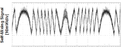
In this type of interferometric configuration the fact is exploited that a small fraction of the light emitted by a laser, after having been reflected by a vibrating target, is re-injected into the laser cavity, where a sort of coherent radiation detection is realized: the power emitted by the laser is in fact modulated both in amplitude (AM) and in frequency (FM), generating a fringes interferometric signal.[4] This signal is a periodic function of the phase
of the back-scattered field, according to the following relation:
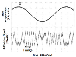
where is the wave number and is the physical distance between the laser source and the moving target. If a phase shift of an entire period is imposed, that is =, we get =. So, if we can see an entire fringe on the oscilloscope screen, we can say that the phase shift due to the movement of the obstacle is , that is /. In this way, by counting the number of visible fringes, it is possible to calculate both the magnitude and the direction of the displacement with a resolution of /. This was first demonstrated in 1978 by Silvano Donati.[5]
Compared to the classic interferometers that refer to Michelson one, this new type of interferometer is considerably simpler, since the laser beam already has all the information related to the signal that is no longer generated by the beating of two beams coming from optical path difference. Therefore, the reference optical path is no longer necessary for measurement and relies only on the interaction between the electric field that travels to the target and the electric field inside the laser cavity.[2]
AM self-mixing laser interferometry


The trend of the amplitude modulated interferometric signal is shown, generated by a vibrating target (such as an audio speaker) powered through a sinusoidal voltage. For the properties of self-mixing laser interferometry, whenever the vibration of a vibrating target is such that its displacement is greater than or equal to / (where is wavelength of employed laser), an interferometric fringe is created. However, with regard to amplitude modulation of the interferometric signal there are basically two consequences:
- through the simple counting of the number of fringes generated, it is possible to retrieve the displacement of the target
- instruments that use only the amplitude modulation (AM) are not very sensitive
The amplitude modulation (AM) of the emitted optical power is detected by the photodiode of monitor (PD) inside the laser package. In this particular interferometric technique the resolution of the displacement and vibration measurement is limited by a low signal-to-noise radio or SNR, such that the system is only suitable for slow and wide measurements .[6]
FM self-mixing laser interferometry


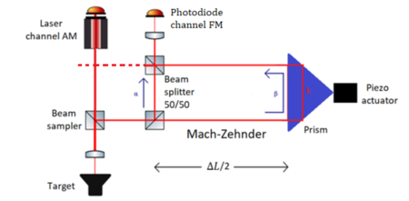
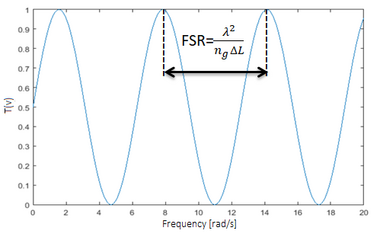
Compared to the reading of the amplitude modulation performed with a photodiode, the reading of the frequency modulation is more complex, since the signal is superimposed on a carrier at the optical frequencies (of the order of THz) invisible to the semiconductor detectors and to the reading electronics, so that techniques (such as a superheterodyne receiver) or complex optical systems to convert frequency modulation into an amplitude modulation would be necessary: in fact by exploiting frequency modulation it would be theoretically possible achieving a higher signal-to-noise ratio and hence a better resolution in the condition of shifts less than half the wavelength. A system capable of converting the frequency modulation into the amplitude one is formed by a Mach-Zehnder interferometer which acts as an optical filter.[2] The shape of the filter transfer function has a perfectly sinusoidal pattern by changing the frequency of the laser; the sinusoidal profile is repeated for the whole spectrum, due to the interference phenomenon on which the operation of the filter is based: [6]
Filter transfer function:
where, is an amplitude coefficient and is the group index. It is possible to carry out the conversion appropriately by calibrating the path difference at any optical frequency (therefore to any laser wavelength). The path difference determines both the Free Spectral Range (FSR) of the instrument, coinciding with the bandwidth between two consecutive peaks of the transfer function, and the filter sensitivity. In particular, if the length of the Mach-Zehnder's path difference is large, then the sensitivity of the filter will be high, so that the converted signal amplitude is increased; while, if the length of the Mach-Zehnder's path difference is small, then the sensitivity of the filter will be low, so that the converted signal amplitude is reduced: [6]
Filter sensitivity:
In order to design the Mach-Zehnder , it is needed achieving a compromise between sensitivity, FSR and dimensions of the filter, taking into account the main sources of noise in the system.[2]
Noise sources
The noise sources that affect the entire system are related to both amplitude and frequency modulation. In particular, the noise sources related to the AM modulation are due both to the dark current noise, to the shot noise and to the electronics of the monitor photodiode, and to the laser shot noise. Similarly, the noise sources related to FM modulation are due not only to the dark current noise, to the shot noise and to that of the FM photodiode electronics, but also to the contribution of noise related to the laser frequency modulation, which is converted into amplitude noise by the Mach-Zehnder interferometer: this latter type of noise is related to the line width of the laser, which is in turn linked to the random phase of the photons emitted by spontaneous emission.
Compatibly with the noise associated with the electronics of the instrument that will be used for the acquisition of AM and FM signals, it will be possible to reduce the path difference and therefore the noise associated with the interferometric signal, as long as the contribution of dominant noise remains that relative to frequency modulation.[2]
References
- ↑ Fan, Yuanlong; Yu, Yanguang; Xi, Jiangtao; Chicharo, Joe F. (2011-09-10). "Improving the measurement performance for a self-mixing interferometry-based displacement sensing system" (in en). Applied Optics 50 (26): 5064–72. doi:10.1364/AO.50.005064. ISSN 0003-6935. PMID 21946986. Bibcode: 2011ApOpt..50.5064F. https://ro.uow.edu.au/infopapers/3630.
- ↑ 2.0 2.1 2.2 2.3 2.4 Norgia, M; Bandi, F; Pesatori, A; Donati, S (May 2019). "High-sensitivity vibrometer based on FM self-mixing interferometry". Journal of Physics: Conference Series 1249 (1): 012020. doi:10.1088/1742-6596/1249/1/012020. ISSN 1742-6588. Bibcode: 2019JPhCS1249a2020N.
- ↑ G. Giuliani, M. Norgia, S. Donati, and T. Bosch (2002). Laser diode selfmixing technique for sensing applications. vol. 4, no. 6. p. S283.
- ↑ Donati, Silvano; Norgia, Michele (October 2017). "Self-Mixing Interferometer With a Laser Diode: Unveiling the FM Channel and Its Advantages Respect to the AM Channel". IEEE Journal of Quantum Electronics 53 (5): 1–10. doi:10.1109/JQE.2017.2744984. ISSN 0018-9197. Bibcode: 2017IJQE...5344984D.
- ↑ S.Donati. "Laser Interferometry by Induced Modulation of the Cavity Field" Journal of Applied Physics vol.49, (1978), pp.495-497.
- ↑ 6.0 6.1 6.2 Norgia, Michele; Melchionni, Dario; Donati, Silvano (2017-09-15). "Exploiting the FM-Signal in a Laser-Diode SMI by Means of a Mach–Zehnder Filter". IEEE Photonics Technology Letters 29 (18): 1552–1555. doi:10.1109/LPT.2017.2735899. ISSN 1041-1135. Bibcode: 2017IPTL...29.1552N.
 |
