Two-tree broadcast
The two-tree broadcast (abbreviated 2tree-broadcast or 23-broadcast) is an algorithm that implements a broadcast communication pattern on a distributed system using message passing. A broadcast is a commonly used collective operation that sends data from one processor to all other processors. The two-tree broadcast communicates concurrently over two binary trees that span all processors. This achieves full usage of the bandwidth in the full-duplex communication model while having a startup latency logarithmic in the number of partaking processors.[1] The algorithm can also be adapted to perform a reduction or prefix sum.
Algorithm
A broadcast sends a message from a specified root processor to all other processors. Binary tree broadcasting uses a binary tree to model the communication between the processors. Each processor corresponds to one node in the tree, and the root processor is the root of the tree. To broadcast a message M, the root sends M to its two children (child nodes). Each processor waits until it receives M and then sends M to its children. Because leaves have no children, they don't have to send any messages. The broadcasting process can be pipelined by splitting the message into k blocks, which are then broadcast consecutively. In such a binary tree, the leaves of the tree only receive data, but never send any data themselves. If the communication is bidirectional (full-duplex), meaning each processor can send a message and receive a message at the same time, the leaves only use one half of the available bandwidth.

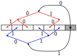
The idea of the two-tree broadcast is to use two binary trees T1 and T2 and communicate on both concurrently.[1] The trees are constructed so that the interior nodes of one tree correspond to leaf nodes of the other tree. The data that has to be broadcast is split into blocks of equal size. In each step of the algorithm, each processor receives one block and sends the previous block to one of its children in the tree in which it is an interior node. A schedule is needed so that no processor has to send or receive two messages in the same step. To create such a schedule, the edges of both trees are colored with 0 and 1 such that
- no processor is connected to its parent nodes in T1 and T2 using edges of the same color
- no processor is connected to its children nodes in T1 or T2 using edges of the same color.
Edges with color 0 are used in even steps, edges with color 1 are used in odd steps.
This schedule allows each processor to send one message and receive one message in each step, fully utilizing the available bandwidth.[1]
Assume that processor i wants to broadcast a message. The two trees are constructed for the remaining processors. Processor i sends blocks alternating to the roots of the two trees, so each tree broadcasts one half of the message.
Analysis
Let p be the number of processing elements (PE), numbered from 0 to p - 1.
Construction of the trees

Let h = ⌈log(p + 2)⌉.
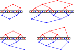
T1 and T2 can be constructed as trees of height h - 1, such that both trees form an in-order numbering of the processors, with the following method:[1]
T1: If p = 2h − 2, T1 is a complete binary tree of height h − 1 except that the rightmost leaf is missing. Otherwise, T1 consists of a complete binary tree of height h − 2 covering PEs [0, 2h−1 − 2], a recursively constructed tree covering PEs [2h−1, p − 1], and a root at PE 2h−1 − 1 whose children are the roots of the left and the right subtree.
T2: There are two ways to construct T2.
With shifting, T2 is first constructed like T1, except that it contains an additional processor. Then T2 is shifted by one position to the left and the leftmost leaf is removed.
With mirroring, T2 is the mirror image of T1 (with the mirror axis between processors p/2−1 and p/2). Mirroring only works for even p.
It can be proven that a coloring with the desired properties exists for all p.[1] When mirroring is used to construct T2, each processor can independently compute the color of its incident edges in O(log p) time.[1]
Communication Time
For this analysis, the following communication model is used: A message of size n has a communication time of α + βn, independent on which processors communicate. α represents the startup overhead to send the message, β represents the transmission time per data element.[2]
Suppose the message of size m is split into 2k blocks. Each communication step takes time α + βm/2k. Let h=log p be the height of the communication structure with the root at processor i and the two trees below it. After 2h steps, the first data block has reached every node in both trees. Afterwards, each processor receives one block in every step until it received all blocks. The total number of steps is 2h + 2k resulting in a total communication time of (2h + 2k)(α + βm/2k). Using an optimal k = k* = (βmh/2α)1⁄2, the total communication time is βm + 2αlog p + √8αβmlog p.
Comparison to similar algorithms
In a linear pipeline broadcast, the message is split into k blocks. In each step, each processor i receives one block from the processor i-1 (mod p) and sends one block to the processor i+1 (mod p). Linear pipeline has optimal throughput, but has a startup time in O(p).[3] For large p, the O(log p) startup latency of the two-tree broadcast is faster. Because both algorithms have optimal throughput, the two-tree algorithm is faster for a large numbers of processors.
A binomial tree broadcast communicates along a binomial tree. Each process receives the message that is broadcast (the root already has the message) and then sends the message to its children. A binomial tree broadcast has only half the startup time of the two-tree broadcast, but a factor of log(p) more communication.[4] The binomial tree broadcast is faster than the two-tree broadcast for small messages, but slower for large messages.

A pipelined binary tree broadcast splits the message into k blocks and broadcasts the blocks consecutively over a binary tree. By using a Fibonacci tree instead of a simple balanced binary tree, the startup latency can be reduced to αlog(p). [5] A Fibonacci tree of height h consists of a root that has a Fibonacci tree of height h-1 as its left child and a Fibonacci tree of h-2 as its right child. The pipelined Fibonacci tree broadcast has half the startup latency of the two-tree broadcast, but also only half of the throughput. It is faster for small messages, while the two-tree broadcast is faster for large messages.
Usage for other communication primitives
Reduction

A reduction (MPI_Reduce in the MPI standard) computes where Mi is a vector of length m originally
available at processor i and is a binary operation that is associative, but not necessarily commutative.
The result is stored at a specified root processor r.
Assume that r = 0 or r = p−1.
In this case the communication is identical to the broadcast, except that the communication direction is reversed.[1]
Each process receives two blocks from its children, reduces them with its own block, and sends the result to its parent.
The root takes turns receiving blocks from the roots of T1 and T2 and reduces them with its own data.
The communication time is the same as for the Broadcast and the amount of data reduced per processor is 2m.
If the reduce operation is commutative, the result can be achieved for any root by renumbering the processors.

If the operation is not commutative and the root is not 0 or p−1, then 2βm is a lower bound for the communication time.[1] In this case, the remaining processors are split into two subgroups. The processors <r perform a reduction to the root r−1 and the processors >r perform a reduction to the root r+1. Processor r receives blocks alternating from the two roots of the subgroups.
Prefix sum
A prefix sum (MPI_Scan) computes for each
processor j where Mi is a vector of length m originally
available at processor i and is a binary associative operation.
Using an inorder binary tree, a prefix sum can be computed by first performing an up-phase in which each interior node computes a partial sum for left- and rightmost leaves l and r, followed by a down-phase in which prefixes of the form are sent down the tree and allow each processor to finish computing its prefix sum.[6][1]
The communication in the up-phase is equivalent to a reduction to processor 0 and the communication in the down-phase is equivalent to a broadcast from the processor 0.
The total communication time is about twice the communication time of the two-tree broadcast.[1]
ESBT broadcast
If p is a power of two, there is an optimal broadcasting algorithm based on edge disjoint spanning binomial trees (ESBT) in a hypercube.[7]
The hypercube, excluding the root 0d, is split into log p ESBTs.
The algorithm uses pipelining by splitting the broadcast data into k blocks.
Processor 0d cyclically distributes blocks to the roots of the ESBTs and each ESBT performs a pipelined binary tree broadcast.
In step i, each processor sends and receives one message along dimension i mod d.
The communication time of the algorithm is βm + αlog p + √4αβmlog p,[7] so the startup latency is only one half of the startup latency of the two-tree broadcast.
The drawback of the ESBT broadcast is that it does not work for other values of p and it cannot be adapted for (non-commutative) reduction or prefix sum.
References
- ↑ 1.00 1.01 1.02 1.03 1.04 1.05 1.06 1.07 1.08 1.09 Sanders, Peter; Speck, Jochen; Träff, Jesper Larsson (2009). "Two-tree algorithms for full bandwidth broadcast, reduction and scan". Parallel Computing 35 (12): 581–594. doi:10.1016/j.parco.2009.09.001. ISSN 0167-8191.
- ↑ Hockney, Roger W. (1994). "The communication challenge for MPP: Intel Paragon and Meiko CS-2". Parallel Computing 20 (3): 389–398. doi:10.1016/S0167-8191(06)80021-9. ISSN 0167-8191.
- ↑ Pješivac-Grbović, Jelena; Angskun, Thara; Bosilca, George; Fagg, Graham E.; Gabriel, Edgar; Dongarra, Jack J. (2007). "Performance analysis of MPI collective operations". Cluster Computing 10 (2): 127–143. doi:10.1007/s10586-007-0012-0. ISSN 1386-7857.
- ↑ Chan, Ernie; Heimlich, Marcel; Purkayastha, Avi; Van De Geijn, Rober (2007). "Collective Communication: Theory, Practice, and Experience". Concurrency and Computation: Practice and Experience 19 (13): 1749–1783. doi:10.1002/cpe.v19:13. ISSN 1532-0626.
- ↑ Bruck, Jehoshua; Cypher, Robert; Ho, C-T (1992). "Multiple message broadcasting with generalized Fibonacci trees". [1992] Proceedings of the Fourth IEEE Symposium on Parallel and Distributed Processing. IEEE. pp. 424–431. doi:10.1109/SPDP.1992.242714. ISBN 978-0-8186-3200-6. https://authors.library.caltech.edu/12404/1/BRUispdp92b.pdf.
- ↑ Sanders, Peter; Träff, Jesper Larsson (2006). "Parallel Prefix (Scan) Algorithms for MPI". Recent Advances in Parallel Virtual Machine and Message Passing Interface. Lecture Notes in Computer Science. 4192. Springer. 49–57. doi:10.1007/11846802_15. ISBN 978-3-540-39110-4.
- ↑ 7.0 7.1 Johnsson, S.L.; Ho, C.-T. (1989). "Optimum broadcasting and personalized communication in hypercubes". IEEE Transactions on Computers 38 (9): 1249–1268. doi:10.1109/12.29465. ISSN 0018-9340.
 |
