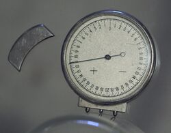
Engineering:Lens clock
A lens clock is a mechanical dial indicator that is used to measure the dioptric power of a lens. It is a specialized version of a spherometer. A lens clock measures the curvature of a surface, but gives the result as an optical power in diopters, assuming the lens is made of a material with a particular refractive index.
How it works
The lens clock has three pointed probes that make contact with the surface of the lens. The outer two probes are fixed while the center one moves, retracting as the instrument is pressed down on the lens's surface. As the probe retracts, the hand on the face of the dial turns by an amount proportional to the distance.
The optical power [math]\displaystyle{ \phi }[/math] of the surface is given by
- [math]\displaystyle{ \phi = {2 (n-1)s \over (D/2)^2}, }[/math]
where [math]\displaystyle{ n }[/math] is the index of refraction of the glass, [math]\displaystyle{ s }[/math] is the vertical distance (sagitta) between the center and outer probes, and [math]\displaystyle{ D }[/math] is the horizontal separation of the outer probes. To calculate [math]\displaystyle{ \phi }[/math] in diopters, both [math]\displaystyle{ s }[/math] and [math]\displaystyle{ D }[/math] must be specified in meters.
A typical lens clock is calibrated to display the power of a crown glass surface, with a refractive index of 1.523. If the lens is made of some other material, the reading must be adjusted to correct for the difference in refractive index.
Measuring both sides of the lens and adding the surface powers together gives the approximate optical power of the whole lens. (This approximation relies on the assumption that the lens is relatively thin.)
Radius of curvature
The radius of curvature [math]\displaystyle{ R }[/math] of the surface can be obtained from the optical power given by the lens clock using the formula
- [math]\displaystyle{ R={(n-1) \over \phi}, }[/math]
where [math]\displaystyle{ n }[/math] is the index of refraction for which the lens clock is calibrated, regardless of the actual index of the lens being measured. If the lens is made of glass with some other index [math]\displaystyle{ n_2 }[/math], the true optical power of the surface can be obtained using
- [math]\displaystyle{ \phi={(n_2-1) \over R}. }[/math]
Example—correcting for refractive index
A biconcave lens made of flint glass with an index of 1.7 is measured with a lens clock calibrated for crown glass with an index of 1.523. For this particular lens, the lens clock gives surface powers of −3.0 and −7.0 diopters (dpt). Because the clock is calibrated for a different refractive index the optical power of the lens is not the sum of the surface powers given by the clock. The optical power of the lens is instead obtained as follows:
First, the radii of curvature are obtained:
- [math]\displaystyle{ R_1={(1.523-1) \over -3.0\ \mathrm{dpt}} =-0.174\ \mathrm{m} }[/math]
- [math]\displaystyle{ R_2={(1.523-1) \over -7.0\ \mathrm{dpt}} =-0.0747\ \mathrm{m} }[/math]
Next, the optical powers of each surface are obtained:
- [math]\displaystyle{ \phi_1={(1.7-1) \over -0.174\ \mathrm{m}}=-4.02\ \mathrm{dpt} }[/math]
- [math]\displaystyle{ \phi_2={(1.7-1) \over -0.0747\ \mathrm{m}}=-9.37\ \mathrm{dpt} }[/math]
Finally, if the lens is thin the powers of each surface can be added to give the approximate optical power of the whole lens: −13.4 diopters. The actual power, as read by a vertometer or lensometer, might differ by as much as 0.1 diopters.
Estimating thickness
A lens clock can also be used to estimate the thickness of thin objects, such as a hard or gas-permeable contact lens. Ideally, a contact lens dial thickness gauge would be used for this, but a lens clock can be used if a dial thickness gauge is not available. To do this, the contact lens is placed concave side up on a table or other hard surface. The lens clock is then brought down on it such that the center prong contacts the lens as close to its center as possible, and the outer prongs rest on the table. The thickness of the lens is then the sagitta [math]\displaystyle{ s }[/math] in the formula above, and can be calculated from the optical power reading, if the distance between the outer prongs is known.
See also
- Astigmatism
- Eyeglass prescription
- Corrective lens
- Galileo
- Lapidary
- George Ravenscroft
- Optometry
- Vertex (optics)
- Clock
- Gear ratio
References
- Heath, Robert S. (1887). A Treatise on Geometrical Optics. Cambridge University Press. https://archive.org/details/cu31924083943872. "Heath A Treatise on Geometrical Optics."
- Hall, M.B. (1975). The Royal Society’s role in the diffusion of information in the seventeenth century. Notes and Records of the Royal Society of London. Royal Society of London.
- Hall, M.B. (1991). Promoting experimental learning: Experiment and the Royal Society 1660–1727. Cambridge, England: Cambridge University Press.
- Heilbron, J. L. (1983). Physics at the Royal Society during Newton’s Presidency. Los Angeles: William Andrews Clark Memorial Library.
- Thomas, T. (1812). History of the Royal Society From Its Institution to the End of the Eighteenth Century. London: The Royal Society.
- Sepper, Dennis L. (1994). Newton’s Optical Writings: A Guided Study. New Brunswick, N.J.: Rutger’s University Press. https://archive.org/details/newtonsopticalwr0000sepp.
pl:Sferometr
 |


