Engineering:Ellipse Law
The Law of the Ellipse, or Stodola's cone law,[1][2] provides a method for calculating the highly nonlinear dependence of extraction pressures with a flow for multistage turbine with high backpressure, when the turbine nozzles are not choked.[3] It is important in turbine off-design calculations.
Description
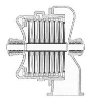
We consider a multistage turbine, like in the picture. The design calculation is done for the design flow rate ([math]\displaystyle{ \scriptstyle \dot m_0 \, }[/math], the flow expected for the most uptime). The other parameters for design are the temperature and pressure at the stage group intake, [math]\displaystyle{ \scriptstyle T_0 \, }[/math] and [math]\displaystyle{ \scriptstyle p_0 \, }[/math], respectively the extraction pressure at the stage group outlet [math]\displaystyle{ \scriptstyle p_2 \, }[/math] (the symbol [math]\displaystyle{ \scriptstyle p_1 \, }[/math] is used for the pressure after a stage nozzle; pressure does not interfere in relations here).
For off-design calculations, the off-design flow rate is [math]\displaystyle{ \scriptstyle \dot m_{01} \, }[/math], respectively, the temperature and pressure at the stage group intake are [math]\displaystyle{ \scriptstyle T_{01} \, }[/math] and [math]\displaystyle{ \scriptstyle p_{01} \, }[/math] and the outlet pressure is [math]\displaystyle{ \scriptstyle p_{21} \, }[/math].
Stodola established experimentally that the relationship between these three parameters as represented in the Cartesian coordinate system has the shape of a degenerate quadric surface, the cone directrix being an ellipse.[4][5] For a constant initial pressure [math]\displaystyle{ \scriptstyle p_{01} \, }[/math] the flow rate depends on the outlet pressure [math]\displaystyle{ \scriptstyle p_{21} \, }[/math] as an arc of an ellipse in a plane parallel to [math]\displaystyle{ \scriptstyle \dot m_{01} \,0\, p_{21} \, }[/math]
For very low outlet pressure [math]\displaystyle{ \scriptstyle p_{21} \, }[/math], like in condensing turbines, flow rates do not change with the outlet pressure, but drops very quickly with the increase in the backpressure. For a given outlet pressure [math]\displaystyle{ \scriptstyle p_{21} \, }[/math], flow rates change depending on the inlet pressure [math]\displaystyle{ \scriptstyle p_{01} \, }[/math] as an arc of hyperbola in a plane parallel to [math]\displaystyle{ \scriptstyle \dot m_{01} \,0\, p_{01} \, }[/math].
Usually, Stodola's cone does not represent absolute flow rates and pressures, but rather maximum flow rates and pressures, with the maximum values of the diagram having in this case the value of 1. The maximum flow rate has the symbol [math]\displaystyle{ \scriptstyle \dot m_{0m} \, }[/math] and the maximum pressures at the inlet and outlet have the symbols [math]\displaystyle{ \scriptstyle p_{0m} \, }[/math] and [math]\displaystyle{ \scriptstyle p_{2m} \, }[/math]. The pressure ratios for the design flow rate at the intake and outlet are [math]\displaystyle{ \scriptstyle \epsilon_0 = p_0 / p_{0m} \, }[/math] and [math]\displaystyle{ \scriptstyle \epsilon_2 = p_2 / p_{2m} \, }[/math], and the off-design ratios are [math]\displaystyle{ \scriptstyle \epsilon_{01} = p_{01} / p_{0m} \, }[/math] and [math]\displaystyle{ \scriptstyle \epsilon_{21} = p_{21} / p_{2m} \, }[/math].
If the speed of sound is reached in a stage, the group of stages can be analyzed until that stage, which is the last in the group, with the remaining stages forming another group of analysis. This division is imposed by the stage working in limited (choked) mode. The cone is shifted in the [math]\displaystyle{ \scriptstyle 0\, p_{02} \, }[/math] axis direction, appearing as a triangular surface, depending on the critical pressure ratio [math]\displaystyle{ \scriptstyle \epsilon_c = p_c / p_{01} \, }[/math], where [math]\displaystyle{ \scriptstyle p_c \, }[/math] is the outlet critical pressure of the stage group.[6][7]
The analytical expression of the flow ratio is:[8]
- [math]\displaystyle{ \frac{\dot m_0}{\dot m_{01}} = \sqrt{\frac{T_{01}}{T_0}} \sqrt{\frac {\epsilon_0^2 (1 - \epsilon_c)^2 - (\epsilon_2 - \epsilon_c \epsilon_0)^2}{\epsilon_{01}^2 (1 - \epsilon_c)^2 - (\epsilon_{21} - \epsilon_c \epsilon_{01})^2}} }[/math]
For condensing turbine the ratio [math]\displaystyle{ \scriptstyle \epsilon_c \, }[/math] is very low, previous relation reduces to:
- [math]\displaystyle{ \frac{\dot m_0}{\dot m_{01}} = \sqrt{\frac{T_{01}}{T_0}} \sqrt{\frac {\epsilon_0^2 - \epsilon_2^2}{\epsilon_{01}^2 - \epsilon_{21}^2}} }[/math]
simplified relationship obtained theoretically by Gustav Flügel (1885–1967).[8][9]
In the event that the variation of inlet temperature is low, the relationship is simplified:
- [math]\displaystyle{ \frac{\dot m_0}{\dot m_{01}} = \sqrt{\frac{\epsilon_0^2 - \epsilon_2^2}{\epsilon_{01}^2 - \epsilon_{21}^2}} }[/math]
For condensing turbines [math]\displaystyle{ \scriptstyle \epsilon_2 \, \approx \, \epsilon_{21} \, \approx \, 0 }[/math], so in this case:
- [math]\displaystyle{ \frac{\dot m_0}{\dot m_{01}} = \frac{\epsilon_0}{\epsilon_{01}} = \frac{p_0}{p_{01}} }[/math]
During operation, the above relations allow the assessment of the flow rate depending on the operating pressure of a stage.
References
- (in Romanian) Gavril Creța, Turbine cu abur și cu gaze [Steam and Gas Turbines], București: Ed. Didactică şi Pedagogică, 1981, 2nd ed. Ed. Tehnică, 1996, ISBN:973-31-0965-7
- (in Romanian) Alexander Leyzerovich, Large Steam Power Turbines, Tulsa, Oklahoma: PennWell Publishing Co., 1997, Romanian version, București: Editura AGIR, 2003, ISBN:973-8466-39-3
Further reading
- (in German) Aurel Stodola, Die Dampfturbinen, Berlin: Springer Verlag, 1903–1924 (six editions)
- Aurel Stodola, Steam and Gas Turbines, New York: McGraw-Hill, 1927
- (in German) Constantin Zietemann, Die Dampfturbinen, 2nd ed., Berlin-Göttingen-Heidelberg: Springer-Verlag, 1955
- Walter Traupel, New general theory of multistage axial flow turbomachines. Translated by Dr. C.W. Smith, Washington D.C. Published by Navy Dept.
- Sydney Lawrence Dixon, Fluid Mechanics and Thermodynamics of Turbomachinery, Pergamon Press Ltd., 1966, 2nd ed. 1975, 3rd ed. 1978 (reprinted 1979, 1982 [twice], 1986, 1986, 1989, 1992, 1995), 4th ed. 1998
Notes
- ↑ Timot Veer, Andreas Ulvestad, Olav Bolland, FRAME, a Tool for Predicting Gas Turbine Condition as well as Reability, Availability Performance , ASME/IGTI TURBOEXPO Conference 2004 June 14–17, Vienna, Austria, GT-2004-53770
- ↑ TU Delft Cycle-Tempo, Reference guide[yes|permanent dead link|dead link}}], tudelft.nl, accessed 2010-11-29
- ↑ D. H. Cooke, On Prediction of Off-Design Multistage Turbine Pressures by Stodola's Ellipse, J. Eng. Gas Turbines Power, July 1985, Volume 107, Issue 3, 596 (11 pages), doi:10.1115/1.3239778
- ↑ Creța, p. 300
- ↑ Leyzerovich, p. 175
- ↑ Creța, p. 301
- ↑ Leyzerovich, p. 176
- ↑ 8.0 8.1 Creța, p. 303
- ↑ Leyzerovich, p. 174
External links


