Physics:Euler's pump and turbine equation
The Euler pump and turbine equations are the most fundamental equations in the field of turbomachinery. These equations govern the power, efficiencies and other factors that contribute to the design of turbomachines. With the help of these equations the head developed by a pump and the head utilised by a turbine can be easily determined. As the name suggests these equations were formulated by Leonhard Euler in the eighteenth century.[1] These equations can be derived from the moment of momentum equation when applied for a pump or a turbine.
Conservation of angular momentum
A consequence of Newton's second law of mechanics is the conservation of the angular momentum (or the “moment of momentum”) which is fundamental to all turbomachines. Accordingly, the change of the angular momentum is equal to the sum of the external moments. The variation of angular momentum [math]\displaystyle{ \rho\cdot Q\cdot r\cdot c_u }[/math] at inlet and outlet, an external torque [math]\displaystyle{ M }[/math] and friction moments due to shear stresses [math]\displaystyle{ M_\tau }[/math] act on an impeller or a diffuser.
Since no pressure forces are created on cylindrical surfaces in the circumferential direction, it is possible to write:
- [math]\displaystyle{ \rho Q (c_{2u} r_2 - c_{1u} r_1) = M + M_{\tau}\, }[/math] (1.13)[2]
- [math]\displaystyle{ c_{2u}=c_2\cos\alpha_2\, }[/math]
- [math]\displaystyle{ c_{1u}=c_1\cos\alpha_1.\, }[/math]
Velocity triangles
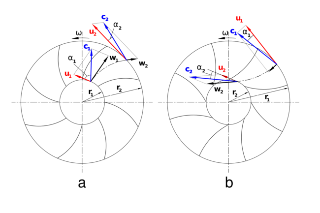
The color triangles formed by velocity vectors u,c and w are called velocity triangles and are helpful in explaining how pumps work.
- [math]\displaystyle{ c_1\, }[/math] and [math]\displaystyle{ c_2\, }[/math] are the absolute velocities of the fluid at the inlet and outlet respectively.
- [math]\displaystyle{ w_1\, }[/math] and [math]\displaystyle{ w_2\, }[/math] are the relative velocities of the fluid with respect to the blade at the inlet and outlet respectively.
- [math]\displaystyle{ u_1\, }[/math] and [math]\displaystyle{ u_2\, }[/math] are the velocities of the blade at the inlet and outlet respectively.
- [math]\displaystyle{ \omega }[/math] is angular velocity.
Figures 'a' and 'b' show impellers with backward and forward-curved vanes respectively.
Euler's pump equation
Based on Eq.(1.13), Euler developed the equation for the pressure head created by an impeller:
- [math]\displaystyle{ Y_{th} = H_t \cdot g = c_{2u} u_2 - c_{1u} u_1 }[/math] (1)
- [math]\displaystyle{ Y_{th}=1/2(u_2^2-u_1^2+w_1^2-w_2^2+c_2^2-c_1^2) }[/math] (2)
Yth : theoretical specific supply ; Ht : theoretical head pressure ; g : gravitational acceleration
For the case of a Pelton turbine the static component of the head is zero, hence the equation reduces to:
- [math]\displaystyle{ H = {1 \over {2g}} ( V_1^2 - V_2^2 ). \, }[/math]
Usage
Euler’s pump and turbine equations can be used to predict the effect that changing the impeller geometry has on the head. Qualitative estimations can be made from the impeller geometry about the performance of the turbine/pump.
This equation can be written as rothalpy invariance:
[math]\displaystyle{ I=h_0-uc_u }[/math]
where [math]\displaystyle{ I }[/math] is constant across the rotor blade.
See also
- Euler equations (fluid dynamics)
- List of topics named after Leonhard Euler
- Rothalpy
References
- ↑ See:
- Euler (1752) "Maximes pour arranger le plus avantageusement les machines destinées à élever de l'eau par moyen des pompes" (Maxims for arranging most advantageously machines intended to raise water by means of pumps), Mémoires de l'Académie Royale des Sciences et des Belles Lettres à Berlin, 8 : 185-232. Here, Euler presents his results for maximizing the outputs of windmills and water wheels, among other means of powering pumps.
- Euler (1754) "Théorie plus complette des machines qui sont mises en mouvement par la réaction de l'eau" (More complete theory of machines that are set in motion by reaction with water), Mémoires de l'Académie Royale des Sciences et des Belles Lettres à Berlin, 10 : 227-295. An analysis of Segner's wheel.
- Euler (1756) "Recherches plus exactes sur l'effect des moulins à vent" (More exact research on the effect [i.e., work output] of windmills), Mémoires de l'Académie Royale des Sciences et des Belles Lettres à Berlin, 12 : 166-234.
- ↑ Johann Friedrich Gülich (2010). Centrifugal Pumps (2nd ed.). Berlin: Springer-Verlag. ISBN 978-3-642-12823-3.
 |


