Engineering:Airbreathing jet engine
An airbreathing jet engine (or ducted jet engine) is a jet engine in which the exhaust gas which supplies jet propulsion is atmospheric air, which is taken in, compressed, heated, and expanded back to atmospheric pressure through a propelling nozzle. Compression may be provided by a gas turbine, as in the original turbojet and newer turbofan, or arise solely from the ram pressure of the vehicle's velocity, as with the ramjet and pulsejet.
All practical airbreathing jet engines heat the air by burning fuel. Alternatively a heat exchanger may be used, as in a nuclear-powered jet engine. Most modern jet engines are turbofans, which are more fuel efficient than turbojets because the thrust supplied by the gas turbine is augmented by bypass air passing through a ducted fan.
Background
The original air-breathing gas turbine jet engine was the turbojet. It was a concept brought to life by two engineers, Frank Whittle in England UK and Hans von Ohain in Germany . The turbojet compresses and heats air and then exhausts it as a high speed, high temperature jet to create thrust. While these engines are capable of giving high thrust levels, they are most efficient at very high speeds (over Mach 1), due to the low-mass-flow, high speed nature of the jet exhaust.
Modern turbofans are a development of the turbojet; they are basically turbojets that include a new section called the fan stage. Rather than using all their exhaust gases to provide direct thrust like a turbojet, turbofan engines extract some of the power from the exhaust gases inside the engine and use it to power the fan stage. The fan stage accelerates a large volume of air through a duct, bypassing the engine core (the actual gas turbine component of the engine), and expelling it at the rear as a jet, creating thrust. A proportion of the air that comes through the fan stage enters the engine core rather than being ducted to the rear, and is thus compressed and heated; some of the energy is extracted to power the compressors and fans, while the remainder is exhausted at the rear. This high-speed, hot-gas exhaust blends with the low speed, cool-air exhaust from the fan stage, and both contribute to the overall thrust of the engine. Depending on what proportion of cool air is bypassed around the engine core, a turbofan can be called low-bypass, high-bypass, or very-high-bypass engines.
Low bypass engines were the first turbofan engines produced, and provide the majority of their thrust from the hot core exhaust gases, while the fan stage only supplements this. These engines are still commonly seen on military fighter aircraft, because they have a smaller frontal area which creates less ram drag at supersonic speeds leaving more of the thrust produced by the engine to propel the aircraft. Their comparatively high noise levels and subsonic fuel consumption are deemed acceptable in such an application, whereas although the first generation of turbofan airliners used low-bypass engines, their high noise levels and fuel consumption mean they have fallen out of favor for large aircraft. High bypass engines have a much larger fan stage, and provide most of their thrust from the ducted air of the fan; the engine core provides power to the fan stage, and only a proportion of the overall thrust comes from the engine core exhaust stream.
Over the last several decades, there has been a move towards very high bypass engines, which use fans far larger than the engine core itself, which is typically a modern, high efficiency two or three-spool design. This high efficiency and power is what allows such large fans to be viable, and the increased thrust available (up to 75,000 lbs per engine in engines such as the Rolls-Royce Trent XWB or General Electric GENx), have allowed a move to large twin engine aircraft, such as the Airbus A350 or Boeing 777, as well as allowing twin engine aircraft to operate on long overwater routes, previously the domain of 3-engine or 4-engine aircraft.
Jet engines were designed to power aircraft, but have been used to power jet cars and jet boats for speed record attempts, and even for commercial uses such as by railroads for clearing snow and ice from switches in railyards (mounted in special rail cars), and by race tracks for drying off track surfaces after rain (mounted in special trucks with the jet exhaust blowing onto the track surface).
Types of airbreathing jet engines
Airbreathing jet engines are nearly always internal combustion engines that obtain propulsion from the combustion of fuel inside the engine. Oxygen present in the atmosphere is used to oxidise a fuel source, typically a hydrocarbon-based jet fuel.[1] The burning mixture expands greatly in volume, driving heated air through a propelling nozzle.
Gas turbine powered engines:
Ram powered jet engine:
Pulsed combustion jet engine:
- pulse detonation engine
- pulse jet engine
- motorjet
Turbojet engine
Two engineers, Frank Whittle in the UK and Hans von Ohain in Germany , developed the turbojet concept independently into practical engines during the late 1930s.
Turbojets consist of an inlet, a compressor, a combustor, a turbine (that drives the compressor) and a propelling nozzle. The compressed air is heated in the combustor and passes through the turbine, then expands in the nozzle to produce a high speed propelling jet[2]
Turbojets have a low propulsive efficiency below about Mach 2[citation needed] and produce a lot of jet noise, both a result of the very high velocity of the exhaust. Modern jet propelled aircraft are powered by turbofans. These engines, with their lower exhaust velocities, produce less jet noise and use less fuel. Turbojets are still used to power medium range cruise missiles[citation needed] due to their high exhaust speed, low frontal area, which reduces drag, and relative simplicity, which reduces cost.
Turbofan engine
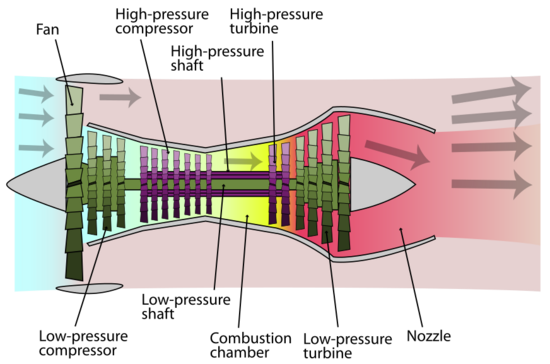
Most modern jet engines are turbofans. The low pressure compressor (LPC), usually known as a fan, compresses air into a bypass duct whilst its inner portion supercharges the core compressor. The fan is often an integral part of a multi-stage core LPC. The bypass airflow either passes to a separate 'cold nozzle' or mixes with low pressure turbine exhaust gases, before expanding through a 'mixed flow nozzle'.
In the 1960s there was little difference between civil and military jet engines, apart from the use of afterburning in some (supersonic) applications. Today, turbofans are used for airliners because they have an exhaust speed that is better matched to the subsonic flight speed of the airliner. At airliner flight speeds, the exhaust speed from a turbojet engine is excessively high and wastes energy. The lower exhaust speed from a turbofan gives better fuel consumption. The increased airflow from the fan gives higher thrust at low speeds. The lower exhaust speed also gives much lower jet noise.
The comparatively large frontal fan has several effects. Compared to a turbojet of identical thrust, a turbofan has a much larger air mass flow rate and the flow through the bypass duct generates a significant fraction of the thrust. The additional duct air has not been ignited, which gives it a slow speed, but no extra fuel is needed to provide this thrust. Instead, the energy is taken from the central core, which gives it also a reduced exhaust speed. The average velocity of the mixed exhaust air is thus reduced (low specific thrust) which is less wasteful of energy but reduces the top speed. Overall, a turbofan can be much more fuel efficient and quieter, and it turns out that the fan also allows greater net thrust to be available at slow speeds.
Thus civil turbofans today have a low exhaust speed (low specific thrust – net thrust divided by airflow) to keep jet noise to a minimum and to improve fuel efficiency. Consequently, the bypass ratio (bypass flow divided by core flow) is relatively high (ratios from 4:1 up to 8:1 are common), with the Rolls-Royce Trent XWB approaching 10:1.[3] Only a single fan stage is required, because a low specific thrust implies a low fan pressure ratio.
Turbofans in civilian aircraft usually have a pronounced large front area to accommodate a very large fan, as their design involves a much larger mass of air bypassing the core so they can benefit from these effects, while in military aircraft, where noise and efficiency are less important compared to performance and drag, a smaller amount of air typically bypasses the core. Turbofans designed for subsonic civilian aircraft also usually have a just a single front fan, because their additional thrust is generated by a large additional mass of air which is only moderately compressed, rather than a smaller amount of air which is greatly compressed.
Military turbofans, however, have a relatively high specific thrust, to maximize the thrust for a given frontal area, jet noise being of less concern in military uses relative to civil uses. Multistage fans are normally needed to reach the relatively high fan pressure ratio needed for high specific thrust. Although high turbine inlet temperatures are often employed, the bypass ratio tends to be low, usually significantly less than 2.0.
Turboprop and turboshaft
Turboprop engines are jet engine derivatives, still gas turbines, that extract work from the hot-exhaust jet to turn a rotating shaft, which is then used to produce thrust by some other means. While not strictly jet engines in that they rely on an auxiliary mechanism to produce thrust, turboprops are very similar to other turbine-based jet engines, and are often described as such.
In turboprop engines, a portion of the engine's thrust is produced by spinning a propeller, rather than relying solely on high-speed jet exhaust. Producing thrust both ways, turboprops are occasionally referred to as a type of hybrid jet engine. They differ from turbofans in that a traditional propeller, rather than a ducted fan, provides the majority of thrust. Most turboprops use gear-reduction between the turbine and the propeller. (Geared turbofans also feature gear reduction, but they are less common.) The hot-jet exhaust is an important minority of thrust, and maximum thrust is obtained by matching the two thrust contributions.[4] Turboprops generally have better performance than turbojets or turbofans at low speeds where propeller efficiency is high, but become increasingly noisy and inefficient at high speeds.[5]
Turboshaft engines are very similar to turboprops, differing in that nearly all energy in the exhaust is extracted to spin the rotating shaft, which is used to power machinery rather than a propeller, they therefore generate little to no jet thrust and are often used to power helicopters.[6]
Propfan
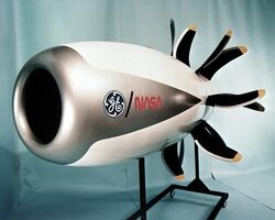
A propfan engine (also called "unducted fan", "open rotor", or "ultra-high bypass") is a jet engine that uses its gas generator to power an exposed fan, similar to turboprop engines. Like turboprop engines, propfans generate most of their thrust from the propeller and not the exhaust jet. The primary difference between turboprop and propfan design is that the propeller blades on a propfan are highly swept to allow them to operate at speeds around Mach 0.8, which is competitive with modern commercial turbofans. These engines have the fuel efficiency advantages of turboprops with the performance capability of commercial turbofans.[7] While significant research and testing (including flight testing) has been conducted on propfans, none have entered production.
Major components
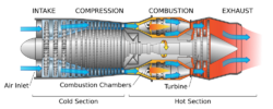
Major components of a turbojet including references to turbofans, turboprops and turboshafts:
Cold Section
- Air intake (Inlet) – For subsonic aircraft, the inlet is a duct which is required to ensure smooth airflow into the engine despite air approaching the inlet from directions other than straight ahead. This occurs on the ground from cross winds and in flight with aircraft pitch and yaw motions. The duct length is minimised to reduce drag and weight.[8] Air enters the compressor at about half the speed of sound so at flight speeds lower than this the flow will accelerate along the inlet and at higher flight speeds it will slow down. Thus the internal profile of the inlet has to accommodate both accelerating and diffusing flow without undue losses. For supersonic aircraft, the inlet has features such as cones and ramps to produce the most efficient series of shockwaves which form when supersonic flow slows down. The air slows down from the flight speed to subsonic velocity through the shockwaves, then to about half the speed of sound at the compressor through the subsonic part of the inlet. The particular system of shockwaves is chosen, with regard to many constraints such as cost and operational needs, to minimise losses which in turn maximises the pressure recovery at the compressor.[9]
- Compressor or Fan – The compressor is made up of stages. Each stage consists of rotating blades and stationary stators or vanes. As the air moves through the compressor, its pressure and temperature increase. The power to drive the compressor comes from the turbine (see below), as shaft torque and speed.
- Bypass ducts deliver the flow from the fan with minimum losses to the bypass propelling nozzle. Alternatively the fan flow may be mixed with the turbine exhaust before entering a single propelling nozzle. In another arrangement an afterburner may be installed between the mixer and nozzle.
- Shaft – The shaft connects the turbine to the compressor, and runs most of the length of the engine. There may be as many as three concentric shafts, rotating at independent speeds, with as many sets of turbines and compressors. Cooling air for the turbines may flow through the shaft from the compressor.
- Diffuser section: – The diffuser slows down the compressor delivery air to reduce flow losses in the combustor. Slower air is also required to help stabilize the combustion flame and the higher static pressure improves the combustion efficiency.[10]
Hot section
- Combustor or Combustion Chamber – Fuel is burned continuously after initially being ignited during the engine start.
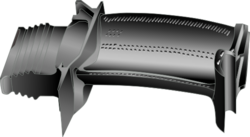
- Turbine – The turbine is a series of bladed discs that act like a windmill, extracting energy from the hot gases leaving the combustor. Some of this energy is used to drive the compressor. Turboprop, turboshaft and turbofan engines have additional turbine stages to drive a propeller, bypass fan or helicopter rotor. In a free turbine the turbine driving the compressor rotates independently of that which powers the propeller or helicopter rotor. Cooling air, bled from the compressor, may be used to cool the turbine blades, vanes and discs to allow higher turbine entry gas temperatures for the same turbine material temperatures.**
- Afterburner or reheat (British) – (mainly military) Produces extra thrust by burning fuel in the jetpipe. This reheating of the turbine exhaust gas raises the propelling nozzle entry temperature and exhaust velocity. The nozzle area is increased to accommodate the higher specific volume of the exhaust gas. This maintains the same airflow through the engine to ensure no change in its operating characteristics.
- Exhaust or Nozzle – Turbine exhaust gases pass through the propelling nozzle to produce a high velocity jet. The nozzle is usually convergent with a fixed flow area.
- Supersonic nozzle – For high nozzle pressure ratios (Nozzle Entry Pressure/Ambient Pressure) a convergent-divergent (de Laval) nozzle is used. The expansion to atmospheric pressure and supersonic gas velocity continues downstream of the throat and produces more thrust.
The various components named above have constraints on how they are put together to generate the most efficiency or performance. The performance and efficiency of an engine can never be taken in isolation; for example fuel/distance efficiency of a supersonic jet engine maximises at about Mach 2, whereas the drag for the vehicle carrying it is increasing as a square law and has much extra drag in the transonic region. The highest fuel efficiency for the overall vehicle is thus typically around Mach 0.85.
For the engine optimisation for its intended use, important here is air intake design, overall size, number of compressor stages (sets of blades), fuel type, number of exhaust stages, metallurgy of components, amount of bypass air used, where the bypass air is introduced, and many other factors. An example is design of the air intake.
Operation
Engine cycle
The thermodynamics of a typical air-breathing jet engine are modeled approximately by a Brayton Cycle which is a thermodynamic cycle that describes the workings of the gas turbine engine, which is the basis of the airbreathing jet engine and others. It is named after George Brayton (1830–1892), the American engineer who developed it, although it was originally proposed and patented by Englishman John Barber in 1791.[11] It is also sometimes known as the Joule cycle.
Thrust lapse
The nominal net thrust quoted for a jet engine usually refers to the Sea Level Static (SLS) condition, either for the International Standard Atmosphere (ISA) or a hot day condition (e.g. ISA+10 °C). As an example, the GE90-76B has a take-off static thrust of 76,000 lbf (360 kN) at SLS, ISA+15 °C.
Naturally, net thrust will decrease with altitude, because of the lower air density. There is also, however, a flight speed effect.
Initially as the aircraft gains speed down the runway, there will be little increase in nozzle pressure and temperature, because the ram rise in the intake is very small. There will also be little change in mass flow. Consequently, nozzle gross thrust initially only increases marginally with flight speed. However, being an air breathing engine (unlike a conventional rocket) there is a penalty for taking on-board air from the atmosphere. This is known as ram drag. Although the penalty is zero at static conditions, it rapidly increases with flight speed, causing the net thrust to be eroded.
As flight speed builds up after take-off, the ram rise in the intake starts to have a significant effect upon nozzle pressure/temperature and intake airflow, causing nozzle gross thrust to climb more rapidly. This term now starts to offset the still increasing ram drag, eventually causing net thrust to start to increase. In some engines, the net thrust at say Mach 1.0, sea level can even be slightly greater than the static thrust. Above Mach 1.0, with a subsonic inlet design, shock losses tend to decrease net thrust, however a suitably designed supersonic inlet can give a lower reduction in intake pressure recovery, allowing net thrust to continue to climb in the supersonic regime.
Safety and reliability
Jet engines are usually very reliable and have a very good safety record. However, failures do sometimes occur.
Engine surge
In some cases in jet engines the conditions in the engine due to airflow entering the engine or other variations can cause the compressor blades to stall. When this occurs the pressure in the engine blows out past the blades, and the stall is maintained until the pressure has decreased, and the engine has lost all thrust. The compressor blades will then usually come out of stall, and re-pressurize the engine. If conditions are not corrected, the cycle will usually repeat. This is called surge. Depending on the engine this can be highly damaging to the engine and creates worrying vibrations for the crew.
Blade containment
Fan, compressor or turbine blade failures have to be contained within the engine casing. To do this the engine has to be designed to pass blade containment tests as specified by certification authorities.[12]
Bird ingestion
Bird ingestion is the term used when birds enter the intake of a jet engine. It is a common aircraft safety hazard and has caused fatal accidents. In 1988 an Ethiopian Airlines Boeing 737 ingested pigeons into both engines during take-off and then crashed in an attempt to return to the Bahir Dar airport; of the 104 people aboard, 35 died and 21 were injured. In another incident in 1995, a Dassault Falcon 20 crashed at a Paris airport during an emergency landing attempt after ingesting lapwings into an engine, which caused an engine failure and a fire in the airplane fuselage; all 10 people on board were killed.[13]
Jet engines have to be designed to withstand the ingestion of birds of a specified weight and number, and to not lose more than a specified amount of thrust. The weight and numbers of birds that can be ingested without hazarding the safe flight of the aircraft are related to the engine intake area.[14] In 2009, an Airbus A320 aircraft, US Airways Flight 1549, ingested one Canada goose into each engine. The plane ditched in the Hudson River after taking off from LaGuardia International Airport in New York City. There were no fatalities. The incident illustrated the hazards of ingesting birds beyond the "designed-for" limit.
The outcome of an ingestion event and whether it causes an accident, be it on a small fast plane, such as military jet fighters, or a large transport, depends on the number and weight of birds and where they strike the fan blade span or the nose cone. Core damage usually results with impacts near the blade root or on the nose cone.
Few birds fly high, so the greatest risk of a bird ingestion is during takeoff and landing and during low level flying.
Volcanic ash
If a jet plane is flying through air contaminated with volcanic ash, there is risk that ingested ash will cause erosion damage to the compressor blades, blockage of fuel nozzle air holes and blockage of the turbine cooling passages. Some of these effects may cause the engine to surge or flame-out during the flight. Re-lights are usually successful after flame-outs but with considerable loss of altitude. It was the case of British Airways Flight 9 which flew through volcanic dust at 37,000 ft. All 4 engines flamed out and re-light attempts were successful at about 13,000 ft.[15]
Uncontained failures
One class of failure that has caused accidents is the uncontained failure, where rotating parts of the engine break off and exit through the case. These high energy parts can cut fuel and control lines, and can penetrate the cabin. Although fuel and control lines are usually duplicated for reliability, the crash of United Airlines Flight 232 was caused when hydraulic fluid lines for all three independent hydraulic systems were simultaneously severed by shrapnel from an uncontained engine failure. Prior to the United 232 crash, the probability of a simultaneous failure of all three hydraulic systems was considered as high as a billion-to-one. However, the statistical models used to come up with this figure did not account for the fact that the number-two engine was mounted at the tail close to all the hydraulic lines, nor the possibility that an engine failure would release many fragments in many directions. Since then, more modern aircraft engine designs have focused on keeping shrapnel from penetrating the cowling or ductwork, and have increasingly utilized high-strength composite materials to achieve the required penetration resistance while keeping the weight low.
Economic considerations
In 2007 the cost of jet fuel, while highly variable from one airline to another, averaged 26.5% of total operating costs, making it the single largest operating expense for most airlines.[16]
Environmental considerations
Jet engines are usually run on fossil fuels and are thus a source of carbon dioxide in the atmosphere. Jet engines can also run on biofuels or hydrogen, although hydrogen is usually produced from fossil fuels.
About 7.2% of the oil used in 2004 was consumed by jet engines.[17]
Nitrogen compounds are also formed during the combustion process from reactions with atmospheric nitrogen. At low altitudes this is not thought to be especially harmful, but for supersonic aircraft that fly in the stratosphere some destruction of ozone may occur.
Sulphates are also emitted if the fuel contains sulphur.
Advanced designs
Ramjet
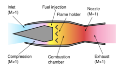
A ramjet is a form of airbreathing jet engine using the engine's forward motion to compress incoming air, without a rotary compressor. Ramjets cannot produce thrust at zero airspeed and thus cannot move an aircraft from a standstill. Ramjets require considerable forward speed to operate well, and as a class work most efficiently at speeds around Mach 3. This type of jet can operate up to speeds of Mach 6.
They consist of three sections; an inlet to compress incoming air, a combustor to inject and combust fuel, and a nozzle to expel the hot gases and produce thrust. Ramjets require a relatively high speed to efficiently compress the incoming air, so ramjets cannot operate at a standstill and they are most efficient at supersonic speeds. A key trait of ramjet engines is that combustion is done at subsonic speeds. The supersonic incoming air is dramatically slowed through the inlet, where it is then combusted at the much slower, subsonic, speeds.[18] The faster the incoming air is, however, the less efficient it becomes to slow it to subsonic speeds. Therefore, ramjet engines are limited to approximately Mach 5.[19]
Ramjets can be particularly useful in applications requiring a small and simple engine for high speed use, such as missiles, while weapon designers are looking to use ramjet technology in artillery shells to give added range: it is anticipated that a 120-mm mortar shell, if assisted by a ramjet, could attain a range of 22 mi (35 km).[20] They have also been used successfully, though not efficiently, as tip jets on helicopter rotors.[21] Pulsejets are subsonic engines which also use ram compression, but with intermittent combustion unlike the continuous combustion used in a ramjet. They are a quite distinct type of jet engine.
Scramjets
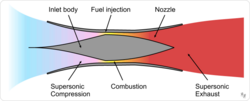
Scramjets are an evolution of ramjets that are able to operate at much higher speeds than any other kind of airbreathing engine. They share a similar structure with ramjets, being a specially shaped tube that compresses air with no moving parts through ram-air compression. They consist of an inlet, a combustor, and a nozzle. The primary difference between ramjets and scramjets is that scramjets do not slow the oncoming airflow to subsonic speeds for combustion. Thus, scramjets do not have the diffuser required by ramjets to slow the incoming airflow to subsonic speeds. They use supersonic combustion instead and the name "scramjet" comes from "Supersonic Combusting Ramjet."
Scramjets start working at speeds of at least Mach 4, and have a maximum useful speed of approximately Mach 17.[22] Due to aerodynamic heating at these high speeds, cooling poses a challenge to engineers.
Since scramjets use supersonic combustion they can operate at speeds above Mach 6 where traditional ramjets are too inefficient. Another difference between ramjets and scramjets comes from how each type of engine compresses the oncoming airflow: while the inlet provides most of the compression for ramjets, the high speeds at which scramjets operate allow them to take advantage of the compression generated by shock waves, primarily oblique shocks.[23]
Very few scramjet engines have ever been built and flown. In May 2010 the Boeing X-51 set the endurance record for the longest scramjet burn at over 200 seconds.[24]
P&W J58 Mach 3+ afterburning turbojet
Turbojet operation over the complete flight envelope from zero to Mach 3+ requires features to allow the compressor to function properly at the high inlet temperatures beyond Mach 2.5 as well as at low flight speeds.[25] The J58 compressor solution was to bleed airflow from the 4th compressor stage at speeds above about Mach 2.[26] The bleed flow, 20% at Mach 3, was returned to the engine via 6 external tubes to cool the afterburner liner and primary nozzle as well as to provide extra air for combustion.[27] The J58 engine was the only operational turbojet engine, being designed to operate continuously even at maximum afterburning, for Mach 3.2 cruise.
An alternative solution is seen in a contemporary installation, which did not reach operational status, the Mach 3 GE YJ93/XB-70. It used a variable stator compressor.[28] Yet another solution was specified in a proposal for a Mach 3 reconnaissance Phantom. This was pre-compressor cooling, albeit available for relatively short duration.[29][30]
Hydrogen-fuelled air-breathing jet engines
Jet engines can be run on almost any fuel. Hydrogen is a highly desirable fuel, as, although the energy per mole is not unusually high, the molecule is very much lighter than other molecules. The energy per kg of hydrogen is twice that of more common fuels and this gives twice the specific impulse. In addition, jet engines running on hydrogen are quite easy to build—the first ever turbojet was run on hydrogen. Also, although not duct engines, hydrogen-fueled rocket engines have seen extensive use.
However, in almost every other way, hydrogen is problematic. The downside of hydrogen is its density; in gaseous form the tanks are impractical for flight, but even in the form of liquid hydrogen it has a density one fourteenth that of water. It is also deeply cryogenic and requires very significant insulation that precludes it being stored in wings. The overall vehicle would end up being very large, and difficult for most airports to accommodate. Finally, pure hydrogen is not found in nature, and must be manufactured either via steam reforming or expensive electrolysis. A few experimental hydrogen-powered aircraft have flown with propellers, and jets have been proposed that may be feasible.[31]
Precooled jet engines
An idea originated by Robert P. Carmichael in 1955[32] is that hydrogen-fueled engines could theoretically have much higher performance than hydrocarbon-fueled engines if a heat exchanger were used to cool the incoming air. The low temperature allows lighter materials to be used, a higher mass-flow through the engines, and permits combustors to inject more fuel without overheating the engine.
This idea leads to plausible designs like Reaction Engines SABRE, that might permit single-stage-to-orbit launch vehicles,[33] and ATREX, which could permit jet engines to be used up to hypersonic speeds and high altitudes for boosters for launch vehicles. The idea is also being researched by the EU for a concept to achieve non-stop antipodal supersonic passenger travel at Mach 5 (Reaction Engines A2).
Turborocket
The air turborocket is a form of combined-cycle jet engine. The basic layout includes a gas generator, which produces high pressure gas, that drives a turbine/compressor assembly which compresses atmospheric air into a combustion chamber. This mixture is then combusted before leaving the device through a nozzle and creating thrust.
There are many different types of air turborockets. The various types generally differ in how the gas generator section of the engine functions.
Air turborockets are often referred to as turboramjets, turboramjet rockets, turborocket expanders, and many others. As there is no consensus on which names apply to which specific concepts, various sources may use the same name for two different concepts.[34]
Terminology
To specify the RPM, or rotor speeds, of a jet engine, abbreviations are commonly used:
- For a turboprop engine, Np refers to the RPM of the propeller shaft. For example, a common Np would be about 2200 RPM for a constant speed propeller.
- N1 or Ng refers to the RPM of the gas generator section. Each engine manufacturer will pick between those two abbreviations. N1 is also used for the fan speed on a turbofan, in which case N2 is the gas generator speed (2 shaft engine). Ng is mainly used for turboprop or turboshaft engines. For example, a common Ng would be on the order of 30,000 RPM.
- N2 or Nf refers to the speed of the power turbine section. Each engine manufacturer will pick between those two abbreviations but N2 is mainly used for turbofan engines whereas Nf is mainly used for turboprop or turboshaft engines. In many cases, even for free turbine engines, the N1 and N2 may be very similar.[citation needed]
- Ns refers to the speed of the reduction gear box (RGB) output shaft for turboshaft engines.[35][36]
In many cases, instead of expressing rotor speeds (N1, N2) as RPM on cockpit displays, pilots are provided with the speeds expressed as a percentage of the design point speed. For example, at full power, the N1 might be 101.5% or 100%. This user interface decision has been made as a human factors consideration, since pilots are more likely to notice a problem with a two- or 3-digit percentage (where 100% implies a nominal value) than with a 5-digit RPM.
See also
- Pump-jet
- Rocket engine
- Turboprop – a gas turbine engine used to turn propellers
- Turboshaft – a gas turbine engine used for helicopters
References
Citations
- ↑ Angelo, Joseph A. (2004). The Facts on File dictionary of space technology (3 ed.). Infobase Publishing. p. 14. ISBN 0-8160-5222-0. https://books.google.com/books?id=kEjNBGzDDfEC&pg=PA14.
- ↑ "Turbojet Engine". NASA Glenn Research Center. http://www.grc.nasa.gov/WWW/K-12/airplane/aturbj.html.
- ↑ "Trent XWB infographic". http://www.rolls-royce.com/customers/civil-aerospace/products/civil-large-engines/trent-xwb/trent-xwb-infographic.aspx.
- ↑ Hill & Peterson 1992, pp. 190.
- ↑ Mattingly 2006, pp. 12–14.
- ↑ Mattingly, p. 12
- ↑ Sweetman, Bill (2005). The Short, Happy Life of the Prop-fan . Air & Space/Smithsonian. 1 September 2005.
- ↑ "Trade-offs in jet inlet design" Andras Sobester Journal of Aircraft, Vol44 No3 May–June 2007
- ↑ "Jet Propulsion for Aerospace Applications" 2nd edition, Walter J.hesse Nicholas V.S. MumfordPitman Publishing Corp 1964 p110
- ↑ "Jet Propulsion for Aerospace Applications" 2nd edition, Walter J.hesse Nicholas V.S. MumfordPitman Publishing Corp 1964 p216
- ↑ according to Gas Turbine History
- ↑ "Part33 Airworthiness Standards- Aircraft Engines" para 33.94 Blade containment and rotor out of balance tests
- ↑ "Transport Canada – Sharing the Skies". Tc.gc.ca. 6 January 2010. http://www.tc.gc.ca/civilaviation/AerodromeAirNav/Standards/WildlifeControl/tp13549/Chapter1.htm.
- ↑ "Part33-Airworthiness Standards-Aircraft Engines section 33.76 Bird ingestion
- ↑ flightglobal archive Flight International 10 July 1982 p59
- ↑ "U.S. Airlines: Operating in an Era of High Jet Fuel Prices". http://www.airlines.org/NR/rdonlyres/73AADEC2-D5A2-4169-B590-1EE83A747CDA/0/Airlines_Fuel.pdf.
- ↑ "How many air-miles are left in the world's fuel tank?". After-oil.co.uk. 29 June 2005. http://www.after-oil.co.uk/runways.htm.
- ↑ Mattingly, p. 14
- ↑ Benson, Tom. Ramjet Propulsion. NASA Glenn Research Center. Updated: 11 July 2008. Retrieved: 23 July 2010.
- ↑ McNab, Chris; Hunter Keeter (2008). Tools of Violence: Guns, Tanks and Dirty Bombs. Osprey Publishing. p. 145. ISBN 978-1-84603-225-7. https://archive.org/details/toolsofviolenceg0000mcna/page/145.
- ↑ "Here Comes the Flying Stovepipe". Time (magazine). 26 November 1965. http://www.time.com/time/magazine/article/0,9171,834721,00.html.
- ↑ "Astronautix X30". Astronautix.com. http://www.astronautix.com/lvs/x30.htm.
- ↑ Heiser, William H.; Pratt, David T. (1994). Hypersonic Airbreathing Propulsion. AIAA Education Series. Washington, D.C.: American Institute of Aeronautics and Astronautics. pp. 23–4. ISBN 978-1-56347-035-6. https://archive.org/details/hypersonicairbre00heis_448.
- ↑ X-51 Waverider makes historic hypersonic flight. United States Air Force. 26 May 2010. Retrieved: 23 July 2010.
- ↑ U.S.Patent 3,344,606 "Recover Bleed Air Turbojet" Robert B. Abernethy
- ↑ sr-71.org Blackbird Manual Section 1 Description and Operation page 1-20
- ↑ enginehistory.org Presentation by Pete Law "SR-71 Propulsion, Part 2"
- ↑ "Jet Propulsion for Aerospace Applications- second edition" Walter J. Hesse, Nicholas V.S. Mumford, Jr. Pitman Publishing corporation. p377
- ↑ aviationtrivia.blogspot.ca "Tails Through Time" J P Santiago Wednesday,18 July 2012 "The Mach 3 Phantom"
- ↑ "F-12 Series Aircraft Propulsion System Performance and Development"David H. Campbell, J.AircraftVol 11, No 11, November 1974
- ↑ e.g. Reaction engines A2 hypersonic airliner
- ↑ "NASA history Other Interests in Hydrogen". Hq.nasa.gov. 21 October 1955. http://www.hq.nasa.gov/pao/History/SP-4404/ch7-13.htm.
- ↑ "The Skylon Spaceplane". http://www.reactionengines.co.uk/tech_docs/JBIS_v57_22-32.pdf.
- ↑ Heiser and Pratt, p. 457
- ↑ PRATT & WHITNEY CANADA MAINTENANCE MANUAL – MANUAL PART NO. 3017042 – Introduction – Page 6
- ↑ Email from subject matter expert – Sr. Field Support Representative, Pratt & Whitney Canada Worldwide Support Network 12 January 2010
Cited sources
- Hill, Philip Graham; Peterson, Carl R. (1992). Mechanics and Thermodynamics of Propulsion (2 ed.). Reading, Massachusetts: Addison-Wesley Publishing Company. ISBN 978-0201146592. https://books.google.com/books?id=8ihcPgAACAAJ. Retrieved 2016-02-13.
- Mattingly, Jack D. (2006). Elements of Propulsion: Gas Turbines and Rockets. AIAA Education Series. Reston, VA: American Institute of Aeronautics and Astronautics. p. 6. ISBN 978-1-56347-779-9.
de:Strahltriebwerk
 |
