Software:Quite Universal Circuit Simulator
 Qucs Logo | |
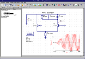
 Screenshot of Qucs | |
| Original author(s) | Michael Margraf, Stefan Jahn et al. |
|---|---|
| Initial release | 8 December 2003 |
| Stable release | 0.0.19
/ 22 January 2017 |
| Preview release | 0.0.20-rc2
/ 23 May 2019[1] |
| Written in | C++ |
| Operating system | Linux, macOS, Solaris, FreeBSD, Windows |
| Type | EDA |
| License | GPL-2.0-or-later |
| Website | qucs |
Quite Universal Circuit Simulator (Qucs) is a free-software electronics circuit simulator software application released under GPL. It offers the ability to set up a circuit with a graphical user interface and simulate the large-signal, small-signal and noise behaviour of the circuit. Pure digital simulations are also supported using VHDL and/or Verilog. Only a small set of digital devices like flip flops and logic gates can be used with analog circuits.[2] Qucs uses its own SPICE-incompatible backend simulator Qucsator, however the Qucs-S fork supports some SPICE backends.
Qucs supports a growing list of analog and digital components as well as SPICE sub-circuits. It is intended to be much simpler to use and handle than other circuit simulators like gEDA or PSPICE.
Analysis types
Analysis types include S-parameter (including noise), AC (including noise), DC, Transient Analysis, Harmonic Balance (not yet finished), Digital simulation (VHDL and Verilog-HDL) and Parameter sweeps.
Features
Qucs has a graphical interface for schematic capture. Simulation data can be represented in various types of diagrams, including Smith-Chart, Cartesian, Tabular, Polar, Smith-Polar combination, 3D-Cartesian, Locus Curve, Timing Diagram and Truth Table.
The documentation offers many useful tutorials (WorkBook), reports (ReportBook) and a technical description of the simulator.
Other features include the transmission line calculator, Filter synthesis, Smith-Chart tool for power and noise matching, Attenuator design synthesis, Device model and subcircuit library manager, Optimizer for analog designs, the Verilog-A interface, Support for multiple languages (GUI and internal help system), Subcircuit (including parameters) hierarchy, Powerful data post-processing possible using equations and symbolically defined nonlinear and linear devices.
Tool suite
Qucs consists of several standalone programs interacting with each other through a GUI.
The GUI is used to create schematics, setup simulations, display simulation results, writing VHDL code, etc.
The analog simulator, gnucsator, is a command line program which is run by the GUI in order to simulate the schematic which you previously setup. It reads a netlist file augmented with commands, performs simulations, and finally produces a dataset file. It can also report errors.
The GUI includes a text editor which can display netlists and simulation logging information. It is handy to edit files related to certain components (e.g. SPICE netlists, or Touchstone files).
A filter synthesis application can help design various types of filters.
The transmission line calculator can be used to design and analyze different types of transmission lines (e.g. microstrips, coaxial cables).
A component library manager gives access to models for real life devices (e.g. transistors, diodes, bridges, opamps). These are usually implemented as macros. The library can be extended by the user.
The attenuator synthesis application can be used to design various types of passive attenuators.
The command line conversion program tool is used by the GUI to import and export datasets, netlists and schematics from and to other CAD/EDA software. The supported file formats as well as usage information can be found on the manpage of qucsconv.
Additionally, the GUI can steer other EDA tools. Analog and mixed simulations can be performed by simulators that read the Qucsator netlist format. For purely digital simulations (via VHDL) the program FreeHDL[3] or Icarus-Verilog can be used. For circuit optimization (minimization of a cost function), ASCO[4] may be invoked.
Components
The following categories of components are provided:
- Lumped components (R, L, C, amplifier, phase shifter, etc.)
- Sources
- Probes
- Transmission lines
- Nonlinear components (diodes, transistors, etc.)
- Digital components
- File containers (S-parameter datasets, SPICE netlists)
- Paintings
There is also a Component library that includes various standard components available in the market (bridges, diodes, varistors, LEDs, JFETs, MOSFETS, and so on).
Transistor models
Qucs supports transistor models, some need to be added by hand. Some have been tested, these include
- FBH-HBT
- HICUM L0 v1.12
- HICUM L0 v1.2
- HICUM L2 v2.1
- HICUM L2 v2.22
- HICUM L2 v2.23
- MESFET (Curtice, Statz, TOM-1 and TOM-2)
- SGP (SPICE Gummel-Poon)
- MOSFET
- JFET
- EPFL-EKV MOSFET v2.6.
Qucs-S
Qucs-S is a fork of Qucs that supports the SPICE-compatible simulator backends of Ngspice, Xyce, SpiceOpus, in addition to Qucsator. Version 2 was released in August 19, 2023.[5]
See also
- Comparison of EDA Software
- List of free electronics circuit simulators
References
- ↑ "Release qucs-0.0.20-rc2 · Qucs/Qucs". https://github.com/Qucs/qucs/releases/tag/qucs-0.0.20-rc2.
- ↑ Brinson, Mike (2006). "A Tutorial: Transient Domain Flip-Flop Models for Mixed-Mode Simulation". https://qucs.sourceforge.net/docs/tutorial/ffmodels.pdf.
- ↑ "FreeHDL index Page". Freehdl.seul.org. http://www.freehdl.seul.org.
- ↑ "ASCO project :: homepage". Asco.sourceforge.net. http://asco.sourceforge.net.
- ↑ "Qucs-S 2.0.0". ra3xdh. https://github.com/ra3xdh/qucs_s/releases/tag/2.0.0.
External links
 |
 |

