Component diagram

| UML diagram types |
|---|
| Structural UML diagrams |
| Behavioral UML diagrams |
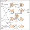
In Unified Modeling Language (UML), a component diagram[1] depicts how components are wired together to form larger components or software systems. They are used to illustrate the structure of arbitrarily complex systems.
Overview
A component diagram allows verification that a system's required functionality is acceptable. These diagrams are also used as a communication tool between the developer and stakeholders of the system. Programmers and developers use the diagrams to formalize a roadmap for the implementation, allowing for better decision-making about task assignment or needed skill improvements. System administrators can use component diagrams to plan ahead, using the view of the logical software components and their relationships on the system.[2]
Diagram elements
The component diagram extends the information given in a component notation element. One way of illustrating a component's provided and required interfaces is through a rectangular compartment attached to the component element.[2] Another accepted way of presenting the interfaces is the ball-and-socket graphic convention. A provided dependency from a component to an interface is illustrated with a solid line to the component using the interface from a "lollipop", or ball, labelled with the name of the interface. A required usage dependency from a component to an interface is illustrated by a half-circle, or "socket", labelled with the name of the interface, attached by a solid line to the component that requires this interface. Inherited interfaces may be shown with a lollipop, preceding the name label with a "caret symbol". To illustrate dependencies between the two, use a "solid line" with an "open arrowhead" joining the socket to the lollipop.[1]
References
- ↑ 1.0 1.1 "Components". Unified Modeling Language 2.5.1. OMG Document Number formal/2017-12-05. Object Management Group Standards Development Organization (OMG SDO). December 2017. p. 208. https://www.omg.org/spec/UML/2.5.1/PDF.
- ↑ 2.0 2.1 Bell, Donald (December 15, 2004). "UML basics: The component diagram". IBM Developer. https://www.ibm.com/developerworks/rational/library/dec04/bell/index.html.
External links
- "Components". Unified Modeling Language 2.5.1. OMG Document Number formal/2017-12-05. Object Management Group Standards Development Organization (OMG SDO). December 2017. p. 208. https://www.omg.org/spec/UML/2.5.1/PDF.
- Component Diagrams in UML 2
- UML 2 Component Diagram Guidelines by Scott W. Ambler
- UML 2 Component Diagrams
| Actors |
|  | |||||||||||
|---|---|---|---|---|---|---|---|---|---|---|---|---|---|
| Concepts |
| ||||||||||||
| Diagrams |
| ||||||||||||
| Derived languages | |||||||||||||
| Other topics | |||||||||||||
 |  |

