Activity diagram

| UML diagram types |
|---|
| Structural UML diagrams |
| Behavioral UML diagrams |
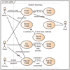
Activity diagrams are graphical representations of workflows of stepwise activities and actions[1] with support for choice, iteration and concurrency. In the Unified Modeling Language, activity diagrams are intended to model both computational and organizational processes (i.e., workflows), as well as the data flows intersecting with the related activities.[2][3] Although activity diagrams primarily show the overall flow of control, they can also include elements showing the flow of data between activities through one or more data stores.[citation needed]
Construction
Activity diagrams are constructed from a limited number of shapes, connected with arrows.[4] The most important shape types:
- stadia represent actions;
- diamonds represent decisions;
- bars represent the start (split) or end (join) of concurrent activities;
- a black circle represents the start (initial node) of the workflow;
- an encircled black circle represents the end (final node).
Arrows run from the start towards the end and represent the order in which activities happen.
Activity diagrams can be regarded as a form of a structured flowchart combined with a traditional data flow diagram. Typical flowchart techniques lack constructs for expressing concurrency.[5] However, the join and split symbols in activity diagrams only resolve this for simple cases; the meaning of the model is not clear when they are arbitrarily combined with decisions or loops.[citation needed]
While in UML 1.x, activity diagrams were a specialized form of state diagrams,[6] in UML 2.x, the activity diagrams were reformalized to be based on Petri net-like semantics, increasing the scope of situations that can be modeled using activity diagrams.[7] These changes cause many UML 1.x activity diagrams to be interpreted differently in UML 2.x.[citation needed]
UML activity diagrams in version 2.x can be used in various domains, e.g. in design of embedded systems. It is possible to verify such a specification using model checking technique.[8]
See also
- Specification and Description Language
- Business Process Modeling Notation
- Control-flow graph
- Data flow diagram
- Drakon-chart
- Event-driven process chain
- List of UML tools
- Pseudocode
- State diagram
- Flowchart
- Activity cycle diagram
References
- ↑ Glossary of Key Terms at McGraw-hill.com. Retrieved 20 July 2008.
- ↑ UML Revision Task Force. OMG Unified Modeling Language Specification, Version 1.4 (final draft). February 2001.
- ↑ J. Rumbaugh, I. Jacobson, and G. Booch. The Unified Modeling Language Reference Manual. Addison-Wesley, 1999.
- ↑ OMG Unified Modeling Language Superstructure Specification, version 2.1.1. Document formal/2007-02-05, Object Management Group, February 2007. http://www.omg.org/cgi-bin/doc?formal/2007-02-05.
- ↑ Jibitesh Mishra and Ashok Mohanty. Software Engineering. Pearson Education, 2011.
- ↑ Dumas, Marlon, and Arthur H.M. Ter Hofstede. "UML activity diagrams as a workflow specification language." ≪ UML≫ 2001—The Unified Modeling Language. Modeling Languages, Concepts, and Tools. Springer Berlin Heidelberg, 2001. 76-90.
- ↑ Störrle, Harald, and J. H. Hausmann. "semantics of uml 2.0 activities." Proceedings of the IEEE Symposium on Visual Languages and Human-Centric Computing. 2004.
- ↑ I. Grobelna, M. Grobelny, M. Adamski, "Model Checking of UML Activity Diagrams in Logic Controllers Design", Proceedings of the Ninth International Conference on Dependability and Complex Systems DepCoS-RELCOMEX, Advances in Intelligent Systems and Computing Volume 286, Springer International Publishing Switzerland, pp. 233-242, 2014
External links
| Actors |
|  | |||||||||||
|---|---|---|---|---|---|---|---|---|---|---|---|---|---|
| Concepts |
| ||||||||||||
| Diagrams |
| ||||||||||||
| Derived languages | |||||||||||||
| Other topics | |||||||||||||
es:Diagrama de actividades
 |  |
