Engineering:Abbe sine condition

In optics, the Abbe sine condition is a condition that must be fulfilled by a lens or other optical system in order for it to produce sharp images of off-axis as well as on-axis objects. It was formulated by Ernst Abbe in the context of microscopes.[1]
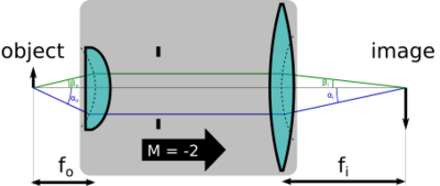
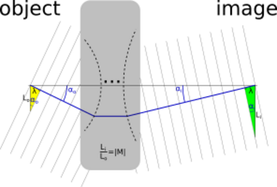
The Abbe sine condition says that
the sine of the object-space angle should be proportional to the sine of the image space angle
Furthermore, the ratio equals the magnification of the system. In mathematical terms this is:
where the variables are the angles (relative to the optic axis) of any two rays as they leave the object, and are the angles of the same rays where they reach the image plane (say, the film plane of a camera). For example, ( might represent a paraxial ray (i.e., a ray nearly parallel with the optic axis), and might represent a marginal ray (i.e., a ray with the largest angle admitted by the system aperture). An optical imaging system for which this is true in for all rays is said to obey the Abbe sine condition.
Magnification and the Abbe sine condition

Using the framework of Fourier optics, we may easily explain the significance of the Abbe sine condition. Say an object in the object plane of an optical system has a transmittance function of the form, T(xo,yo). We may express this transmittance function in terms of its Fourier transform as
where is the exponential function, and is the imaginary unit.
Now, assume for simplicity that the system has no image distortion, so that the image plane coordinates are linearly related to the object plane coordinates via the relation
where M is the system magnification. The object plane transmittance above can now be re-written in a slightly modified form:
where the various terms have been simply multiplied and divided in the exponent by M, the system magnification. Now, the equations may be substituted above for image plane coordinates in terms of object plane coordinates, to obtain,
At this point another coordinate transformation can be proposed (i.e., the Abbe sine condition) relating the object plane wavenumber spectrum to the image plane wavenumber spectrum as
to obtain the final equation for the image plane field in terms of image plane coordinates and image plane wavenumbers as:
From Fourier optics, it is known that the wavenumbers can be expressed in terms of the spherical coordinate system as
If a spectral component is considered for which , then the coordinate transformation between object and image plane wavenumbers takes the form
This is another way of writing the Abbe sine condition, which simply reflects the classical uncertainty principle for Fourier transform pairs, namely that as the spatial extent of any function is expanded (by the magnification factor, M), the spectral extent contracts by the same factor, M, so that the space-bandwidth product remains constant.
See also
- Lagrange invariant
- Smith-Helmholtz invariant
- Herschel's condition
References
- ↑ Abbe, Ernst (June 1881). "On the Estimation of Aperture in the Microscope.". Journal of the Royal Microscopical Society 1 (3): 388–423. doi:10.1111/j.1365-2818.1881.tb05909.x.
 |
