Engineering:Bridge circuit
A bridge circuit is a topology of electrical circuitry in which two circuit branches (usually in parallel with each other) are "bridged" by a third branch connected between the first two branches at some intermediate point along them. The bridge was originally developed for laboratory measurement purposes and one of the intermediate bridging points is often adjustable when so used. Bridge circuits now find many applications, both linear and non-linear, including in instrumentation, filtering and power conversion.[1][2]
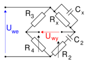
The best-known bridge circuit, the Wheatstone bridge, was invented by Samuel Hunter Christie and popularized by Charles Wheatstone, and is used for measuring resistance. It is constructed from four resistors, two of known values R1 and R3 (see diagram), one whose resistance is to be determined Rx, and one which is variable and calibrated R2. Two opposite vertices are connected to a source of electric current, such as a battery, and a galvanometer is connected across the other two vertices. The variable resistor is adjusted until the galvanometer reads zero. It is then known that the ratio between the variable resistor and its neighbour R1 is equal to the ratio between the unknown resistor and its neighbour R3, which enables the value of the unknown resistor to be calculated.
The Wheatstone bridge has also been generalised to measure impedance in AC circuits, and to measure resistance, inductance, capacitance, and dissipation factor separately. Variants are known as the Wien bridge, Maxwell bridge, and Heaviside bridge (used to measure the effect of mutual inductance).[3] All are based on the same principle, which is to compare the output of two potential dividers sharing a common source.
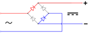
In power supply design, a bridge circuit or bridge rectifier is an arrangement of diodes or similar devices used to rectify an electric current, i.e. to convert it from an unknown or alternating polarity to a direct current of known polarity.
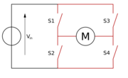
In some motor controllers, an H-bridge is used to control the direction the motor turns.
Bridge current equation

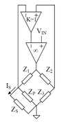
From the figure to the right, the bridge current is represented as I5.
Per Thévenin's theorem, finding the Thévenin equivalent circuit which is connected to the bridge load R5 and using the arbitrary current flow I5, we have:
Thevenin Source (Vth) is given by the formula:
and the Thevenin resistance (Rth):
Therefore, the current flow (I5) through the bridge is given by Ohm's law:
and the voltage (V5) across the load (R5) is given by the voltage divider formula:
See also
- Phantom circuit - a use of balanced bridge circuits in telephony
- Lattice filter - an application of bridge topology to all-pass filters
- Salt bridge
Gallery
-

-
-

-
-
-
-
-
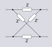 Lattice bridge
 -
 Bridged T circuit
 -

-


_Bridge_T.svg)


References
- ↑ Bureau of Naval Personnel, Basic Electricity, p.114, Courier Dover Publications, 1970 ISBN 0-486-20973-3.
- ↑ Clarence W. De Silva, Vibration monitoring, testing, and instrumentation, pp.2.43-2.49, CRC Press, 2007 ISBN 1-4200-5319-1
- ↑ All about circuits: AC bridge circuits
External links
- Jim Williams, "Bridge circuits: Marrying gain and balance", Linear Technology Application Note 43, June 1990.
- Bridge circuits - Chapter 8 from an online book.
 |  |

