Engineering:FASTRAC
 | |
| Names | FASTRAC 1 ("Sara-Lily") FASTRAC 2 ("Emma") |
|---|---|
| Mission type | Technology demonstration Amateur radio |
| Operator | University of Texas at Austin |
| COSPAR ID | 2010-062F & 2010-062M |
| SATCAT no. | 37227 & 37380 |
| Spacecraft properties | |
| Manufacturer | University of Texas at Austin |
| Launch mass | Total: 58 kg (127 lb)[1] |
| Start of mission | |
| Launch date | 20 November 2010, 01:21 UTC[2] |
| Rocket | Minotaur IV Flight 3 |
| Launch site | Kodiak Launch Complex |
| Contractor | Orbital Sciences |
| End of mission | |
| Disposal | Decommissioned[3] |
| Orbital parameters | |
| Reference system | Geocentric |
| Regime | Low Earth |
| Perigee altitude | 641 km |
| Apogee altitude | 652 km |
| Inclination | 72° |
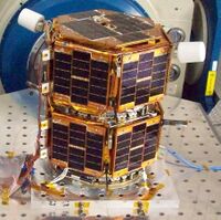
Formation Autonomy Spacecraft with Thrust, Relnav, Attitude and Crosslink (or FASTRAC) is a pair of nanosatellites (respectively named Sara-Lily and Emma) developed and built by students at The University of Texas at Austin. The project is part of a program sponsored by the Air Force Research Laboratory (AFRL), whose goal is to lead the development of affordable space technology. The FASTRAC mission will specifically investigate technologies that facilitate the operation of multiple satellites in formation. These enabling technologies include relative navigation, cross-link communications, attitude determination, and thrust. Due to the high cost of lifting mass into orbit, there is a strong initiative to miniaturize the overall weight of spacecraft. The utilization of formations of satellites, in place of large single satellites, reduces the risk of single point failure and allows for the use of low-cost hardware.
In January 2005, the University of Texas won the University Nanosat-3 Program, a grant-based competition that included 12 other participating universities.[4] As a winner, FASTRAC was given the opportunity to launch its satellites into space. The student-led team received $100,000 from AFRL for the competition portion of the project, and another $100,000 for the implementation phase. FASTRAC is the first student-developed satellite mission incorporating on-orbit real-time relative navigation, on-orbit real-time attitude determination using a single GPS antenna, and a micro-discharge plasma thruster.
FASTRAC launched on 19 November 2010 aboard a Minotaur IV rocket from the Kodiak Launch Complex in Kodiak, Alaska.[5] Separation of the satellites from each other and cross-link communication were successfully carried out.[6]
FASTRAC was developed under the US Air Force Research Laboratory University Nanosatellite Program, and was ranked number 32 in the Space Experiments Review Board's list of prioritised spacecraft experiments in 2006. The spacecraft were expected to demonstrate Global Positioning System relative navigation and micro-charge thruster performance.
Operations
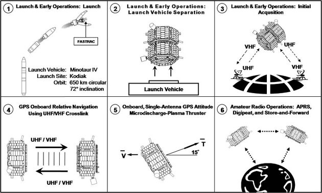
The main mission sequence is composed of six distinct phases: Launch, Launch Vehicle Separation, Initial Acquisition, GPS Onboard Relative Navigation, Onboard Single Antenna GPS Attitude Determination and Micro-discharge Plasma Thruster Operation, and Amateur Radio Operations. In the first phase, the two nanosatellites will be launched on the Department of Defense Space Test Program STP-S26 Mission from Kodiak Launch Complex (KLC) in Kodiak, Alaska. They will be transported to a 72 degree inclination circular low Earth orbit with an altitude of 650 km by a Minotaur IV rocket. Initially, the two nanosatellites will be in a stacked configuration. Once the rocket reaches the desired orbit, the satellites will be powered on by the launch vehicle before finally separating from the launch vehicle.
The third phase will begin once the two nanosatellites are ejected from the rocket. During this phase, there will be a 30-minute period where the satellites will go through a check out and initialization process. After this period, the satellites will begin transmitting beacon messages containing telemetry information that will help determine each satellite's status. During this phase the ground station will attempt to establish first contact with the satellites and perform a check out procedure to make sure all the subsystems on board are working correctly. It is expected that this checkout procedure will take several hours or even a few days depending on the duration of the communication passes with the ground station. Once the operators are satisfied with the status of the satellites, the satellites will be commanded from the ground to separate, finalizing the third phase of the mission.
When the satellites have successfully separated, the primary mission will begin, signaling the start of fourth phase. First, the satellites will autonomously establish a cross-link, or in other words, they will communicate with each other through UHF/VHF bands. The satellites will then exchange GPS data through this cross-link in order to calculate on-orbit real time relative navigation solutions.[7]
The fifth phase will activate a micro-discharge plasma thruster with a command from the ground that will autonomously operate when the thrusting vector is within a 15 degree cone of the anti-velocity vector. The thruster operation will be dependent on the on-orbit real-time single antenna GPS attitude determination solution. After this phase is over, a command from the ground station will disable the thruster on FASTRAC 1.
The final phase of the mission will start once the communication architecture of the satellites is reconfigured from the ground to work with the Automatic Packet Reporting System (APRS) network. This will make the satellites available to amateur radio users all around the world. Once the ground station loses all communication with the satellites, the mission will be terminated and the satellites will passively de-orbit, burning up in the atmosphere. The FASTRAC team has estimated that it will take six months to successfully achieve its mission objectives.
Subsystems
Structure
The structure of the FASTRAC satellites is a hexagonal iso-grid design that is composed of two titanium adapter plates, aluminum 6061 T-6 side panels, six hollow outer columns with inserts and six inner columns. The mass of the two nanosatellites is approximately 127 lbs with all of the components included.
Communication Architecture
The communications architecture is based on a system flown on PCSat2. The FASTRAC implementation consists of two receivers, one transmitter, a terminal node controller (TNC), a transmitter relay board, and a receiver relay board. On FASTRAC 1 “Sara Lily”, two R-100 VHF receivers and one TA-451 UHF transmitter from Hamtronics are used. On FASTRAC 2 “Emma”, two R-451 UHF receivers and one TA-51 VHF transmitter from Hamtronics are used. The TNC used is a KPC-9612+ from Kantronics. Both the transmitter and receiver relay boards were designed and manufactured in house.
Command & Data Handling
The command & data handling (C&DH) system is composed by four distributed AVRs which were developed by Santa Clara University. Each AVR has an Atmega 128 microcontroller and controls an individual subsystem on the satellite (i.e.: COM, EPS, GPS, and THR or IMU). The AVRs communicate with each other through the I2C bus.
GPS Subsystem
The GPS position and attitude determination system was designed and built by student researchers at The University of Texas' GPS Research Lab. The system utilizes GPS code measurements, as well as antenna signal-to-noise ratio (SNR) and 3-axis magnetometer measurements to provide estimates of position, velocity, and attitude. Each satellite will have redundant ORION GPS receivers, dual cross-strapped antennas with RF switching and splitting hardware.
Power System
The power system for each satellite is composed of eight solar panels, a VREG box, and a battery box. The battery box is made from black anodized aluminum and holds 10 Sanyo N4000-DRL D-cells provided to the team by AFRL. Both the solar panels and the VREG board were designed and made in-house. On each satellite, the VREG board distributes power from three VICOR VI-J00 voltage regulators, and also charges the batteries with the power collected from the solar panels.
Separation System
There are two separation systems for the FASTRAC satellites, both designed and manufactured by Planetary Systems Corporation (PSC), which will be used to separate the satellites in their stacked configuration from the Launch Vehicle and then to separate the two satellites while they are in orbit. The PSC Lightband Separation System is composed of two spring-loaded rings and a motorized release mechanism.
Micro-Discharge Plasma Thruster
The micro-discharge plasma thruster was designed and built at UT-Austin. The thruster channels and superheats an inert gas through a micro-channel nozzle producing a micro-Newton level of thrust. It uses a custom made composite tank from CTD. The operation of the thruster will be automated by the spacecraft C&DH using the attitude measurements provided by the GPS attitude determination system. After enabling the operation of the thruster from the ground, it will be only be active when one of the two nozzles is within a 15 degree cone of the anti-velocity vector. The thruster subsystem is only present on FASTRAC 1 "Sara Lily".
Inertial Measurement Unit (IMU)
On FASTRAC 2 “Emma”, instead of using a thruster, an Inertial Measurement Unit (IMU) MASIMU01 from Micro Aerospace Solutions is used to measure the separation of the two satellites.
Amateur Radio Participation
The FASTRAC satellites transmit and receive data (GPS, Health, etc.) on amateur radio frequencies. All amateur radio operators are encouraged to downlink data from either satellite and upload the data to the radio operator section on the FASTRAC Website .[8]
Operation Frequencies
| FASTRAC 1 "Sara Lily" | FASTRAC 2 "Emma" | |
|---|---|---|
| Downlink | 437.345 MHz FM | 145.825 MHz FM |
| Beacon | 437.345 MHz AX.25 1200 AFSK | 145.825 MHz AX.25 1200 AFSK |
| Uplink (1200 Baud) | 145.980 MHz FM | 435.025 MHz FM |
| Uplink (9600 Baud) | 145.825 MHz FM | 437.345 MHz FM |
References
- ↑ "FASTRAC: Press Kit 2010". University of Texas at Austin. http://fastrac.ae.utexas.edu/FASTRAC_PressKit_Nov2010.pdf.
- ↑ Muñoz, Sebastián; Greenbaum, Jamin; Lightsey, Glenn; Stewart, Shaun; Holt, Greg (2011). "The FASTRAC Mission: Operations Summary and Preliminary Experiment Results". 25th AIAA/USU Conference on Small Satellites. 9 August 2011. Logan, Utah.. https://www.researchgate.net/publication/260798212. See also https://digitalcommons.usu.edu/smallsat/2011/all2011/24/.
- ↑ "Past Missions". Texas Spacecraft Laboratory, University of Texas at Austin. https://sites.utexas.edu/tsl/past-missions/.
- ↑ "FASTRAC Project Overview". University of Texas at Austin. 2010-11-02. http://fastrac.ae.utexas.edu/our_project/overview.php.
- ↑ Muñoz, Sebastian (2010-11-02). "FASTRAC News Archive". University of Texas at Austin. http://fastrac.ae.utexas.edu/news/recent.php.
- ↑ First student-developed mission in which satellites orbit and communicate led by UT students, University of Texas at Austin press release, 24 March 2011.
- ↑ Smith, A., Muñoz, S., Hagen, E., Johnson, G.P., & Lightsey, E.G. (2008, August) "The FASTRAC Satellites: Software Implementation and Testing". http://fastrac.ae.utexas.edu/documentation/Smith_SSC08-XII-4.pdf. 22nd Annual USU/AIAA Small Satellite Conference, Logan, Utah, SSC08-XII-4.
- ↑ "FASTRAC Media Kit". http://fastrac.ae.utexas.edu/FASTRAC_PressKit_Nov2010.pdf.
 |


