Engineering:Grid dip oscillator
- "Dip meter" can also refer to an influential early commercial expert system called Dipmeter Advisor; or may refer to an instrument that measures the magnetic dip angle of Earth's magnetic field, the field line angle in a vertical plane.

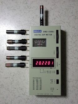
Grid dip oscillator (GDO), also called grid dip meter, gate dip meter, dip meter, or just dipper, is a type of electronic instrument that measures the resonant frequency of nearby unconnected radio frequency tuned circuits. It is a variable-frequency oscillator that circulates a small-amplitude signal through an exposed coil, whose electromagnetic field can interact with adjacent circuitry. The oscillator loses power when its coil is near a circuit that resonates at the same frequency. A meter on the GDO registers the amplitude drop, or "dip", hence the name.
Dip oscillators have been widely used by amateur radio operators for measuring the properties of resonant circuits, filters, and antennas. They can also be used for transmission line testing, as signal generators, and for measuring inductance and capacitance of components. Measurement with a GDO is called "dipping" a circuit.[1]
Principle of operation

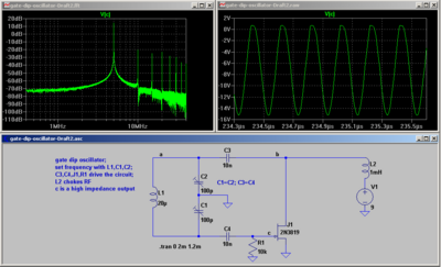
Central to the dip meter is a high-frequency variable-frequency oscillator with a calibrated tuning capacitor and matching interchangeable coils, as shown in the circuit diagram on the right. Resonance is indicated by a dip in amplitude of the signal within the GDO, by a meter on the device.
When the oscillator's exposed coil is in the vicinity of another resonant circuit, the coupled pair behaves as a low-Q transformer whose coupling is most effective when their respective resonant frequencies match. The degree of coupling affects the frequency and amplitude of oscillation in the dip meter, which is sensed in any of several ways, the simplest and most usual of which is a built-in microammeter. The distance between the coil and the tested circuit needs to be adjusted carefully so that the GDO amplitude is significantly affected by the coupled circuit, but its frequency is not.[1][2]: 1–8
History
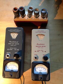
Grid dip oscillators were first developed in the 1920s and were built with vacuum tubes. The devices displayed the amplitude of the tube's grid current, hence the "G" in GDO.
Modern dip meters are solid-state devices, and are sometimes called gate dip oscillators or emitter dip oscillators in reference to the analogous part of the transistor whose current is measured instead of a vacuum tube grid.[1] Solid-state versions of the grid dip oscillator are more versatile, since they can operate at higher Q and lower amplitude, and are not tethered by a power cord.
Dip meters of all types are being supplanted by antenna analyzers, which are more complex, but perform many of the same functions more conveniently, and require less dexterity.[3]
Operation

The dip meter can be used either to measure the relative power lost to a nearby circuit (in which case the amplitude shown on the meter "dips") or to measure the relative power absorbed from a nearby powered circuit (in which case, the meter amplitude peaks). In either mode of operation, some experimentation is needed to find a distance between the pickup coil and the circuit under test, to ensure that the two circuits are close enough to transfer power, but not coupled so closely that the circuit supplied with power overwhelms the responding circuit, and forces it to oscillate regardless of the frequency.[4]
The art of coupling distance
The heart of the instrument is a tunable LC circuit whose exposed external coil will loosely couple to the measured resonant circuit when held moderately close by. The measuring distance must be skillfully adjusted to be close enough to provide sufficient coupling for the dip to show clearly, but far enough that the meter and the tested circuit oscillate independently, so neither device's frequency is significantly distorted by the other, and so that power lost to the external circuit does not swamp the dip meter's oscillator.
The coil and the test circuit can either be inductively or capacitively coupled: Coupling is inductive if the coil wires are held parallel to the nearest wires of the circuit being tested, capacitive if the coil wires and the circuit wires are held perpendicular. Depending on the context desired for the measurement, the circuit under test can be temporarily disconnected from its surroundings to avoid distortion by the parts it is normally attached to, or left wired in place to measure the response of the combined system.
Emission frequency meter
In ordinary use, only the oscillator in the dip meter is powered, and the circuit under test's only power is what it drains from the signal in the GDO coil. When both circuits are resonant at the same frequency, power transfer from the coil to the adjacent tested circuit reaches a maximum, consequently the dip meter's oscillator amplitude reaches a minimum due to the power lost to the circuit under test.[1]: 25–10
The operator adjusts the frequency of the GDO until its meter shows its lowest reading (the "dip"). The frequency is read from the dial on the GDO, or the frequency can be measured by finding the dip meter's signal on a well-calibrated radio receiver. Some modern GDOs have a built-in frequency meter, which makes over-coupling somewhat less troublesome.[1]
Absorption frequency meter
Some dip meters can be used in reverse, as ultra-short-range, tuned field strength meters. The operator finds the frequency at which the highest rise in meter power occurs in the unpowered GDO, when its coil is held near the wires of an active resonant circuit. Since the power in the circuit under test must be high enough to register on the meter, this uncommon method is risky both for the operator and the equipment.
See also
External links
References
- ↑ 1.0 1.1 1.2 1.3 1.4 Silver, H. Ward, ed (2012). The 2013 ARRL Handbook for Radio Communications (90th ed.). Newington, CT: American Radio Relay League. ISBN 978-0-87259-419-7.
- ↑ Houck, Harry W.; Gaw, Norman W. Jr. (Dec 1961). "New method of accurate frequency measurement". Proceedings of the Radio Club of America 37 (4). https://worldradiohistory.com/Archive-Radio-Club-of-America/Radio-Club-of-America-1961-12.pdf. Retrieved 2021-11-12.
- ↑ Hallas, Joel R. W1ZR (August 2016). "Antenna analyzers - the basics". QST (Newington, CT: American Radio Relay League): 32–34. ISSN 0033-4812.
- ↑ Kenwood DM-81 Dip Meter Users' Manual. Komagane, Japan: Kenwood Electronic Inc.. 2005-01-24. pp. 1, 7–10.
 |
