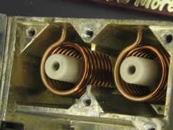
Engineering:Helical resonator

A helical resonator is a passive electrical component that can be used as a filter resonator.
Physically, a helical resonator is a wire helix surrounded by a square or cylindrical conductive shield. One end of the helix is connected to the shield and the other end is left open (Weston, 2001, p. 660). The device works like a coaxial resonator, but it is much shorter because the helical inner conductor reduces the velocity of wave propagation (Lancaster, 2006, p. 99).
Like cavity resonators, helical resonators can achieve Q factors in the 1000s. This is because at high frequencies, the skin effect results in most of the current flowing on the surface of the helix and shield. Plating the shield walls and helix with high conductivity materials increases the Q beyond that of bare copper (Blattenberger, 1989).
The length of wire is one quarter of the wavelength of interest. The helix is space wound, the gap between turns is equal to the diameter of the wire (Blattenberger, 1989). If the open end of the helix is close to the end cap of the metal shield the length is somewhat reduced due to the capacitance between the conductor and the shield (Whittaker, 2000, p. 227).
Coupling to the resonator can be achieved with a tap wire soldered to the helix at some distance from the shorted end. Input impedance varies with distance from the shorted end by impedance transformer action. The tap point is chosen to achieve an impedance match with the connected circuit. Tuning of the resonator may be achieved by inserting a screw into the central axis of the helix (Weston, 2001, p. 660). Other means of input and output coupling used are a wire loop coupling to the magnetic field near the shorted end, or a probe capacitively coupling near the open end. Coupling between resonators in a multi-resonator filter is often simply achieved with apertures in the shielding between them (Whittaker, 2000, p. 227).
Helical resonators are well suited to UHF frequencies ranging from 600 MHz to 1500 MHz (Blattenberger, 1989).
Design equations
- Q - quality factor (dimensionless)
- - resonator characteristic impedance (Ohms)
- d - mean helix diameter (cm)
- h - height of helix (cm)
- f - frequency (MHz)
(Blattenberger, 1989)
References
- Kirt Blattenberger, "Helical resonator design", RF Cafe, 1989.
- M. J. Lancaster, Passive Microwave Device Applications of High-Temperature Superconductors, Cambridge University Press, 2006 ISBN 0521034175.
- David Weston, Electromagnetic Compatibility: Principles and Applications, Second Edition, CRC Press, 2001 ISBN 0824788893.
- Jerry C. Whitaker, The Resource Handbook of Electronics, CRC Press, 2000 ISBN 1420036866.
- Anatol I. Zverev, Handbook of filter synthesis, pp.499-519, Wiley, 1967 OCLC 972252.
 |
