Engineering:Isolation amplifier
Isolation amplifiers are a form of differential amplifier that allow measurement of small signals in the presence of a high common mode voltage by providing electrical isolation and an electrical safety barrier. They protect data acquisition components from common mode voltages, which are potential differences between instrument ground and signal ground. Instruments that are applied in the presence of a common mode voltage without an isolation barrier allow ground currents to circulate, leading in the best case to a noisy representation of the signal under investigation. In the worst case, assuming that the magnitude of common mode voltage or current is sufficient, instrument destruction is likely. Isolation amplifiers are used in medical instruments to ensure isolation of a patient from power supply leakage current.[1]
Amplifiers with an isolation barrier allow the front-end of the amplifier to float with respect to common mode voltage to the limit of the barrier's breakdown voltage, which is often 1,000 volts or more. This action protects the amplifier and the instrument connected to it, while still allowing a reasonably accurate measurement.
These amplifiers are also used for amplifying low-level signals in multi-channel applications. They can also eliminate measurement errors caused by ground loops. Amplifiers with internal transformers eliminate external isolated power supply. They are usually used as analogue interfaces between systems with separated grounds.
Isolation amplifiers may include isolated power supplies for both the input and output stages, or may use external power supplies on each isolated portion.[1]
Concepts
Signal source components

All signal sources are a composite of two major components. The normal mode component (VNM) represents the signal of interest and is the voltage that is applied directly across the inputs of the amplifier. The common mode component (VCM) represents the difference in potential between the low side of the normal mode component and the ground of the amplifier that is used to measure the signal of interest (the normal mode voltage).
In many measurement situations the common mode component is irrelevantly low, but rarely zero. Common mode components of only a few millivolts are frequently encountered and largely and successfully ignored, especially when the normal mode component is orders of magnitude larger.
The first indicator that common mode voltage magnitude is competing with the normal mode component is a noisy reproduction of the latter at the amplifier's output. Such a situation does not usually define the need for an isolation amplifier, but rather a differential amplifier. Since the common mode component appears simultaneously and in phase on both amplifier inputs, the differential amplifier, within the limits of the amplifier's design, can reject it.
However, if the sum of the normal mode and common mode voltages exceeds either the differential amplifier's common mode range, or maximum range without damage then the need for an isolation amplifier is firmly established.
Operating principles
Isolation amplifiers are commercially available as hybrid integrated circuits made by several manufacturers. There are three methods of providing isolation.
A transformer-isolated amplifier relies on transformer coupling of a high-frequency carrier signal between input and output. Some models also include a transformer-isolated power supply, that may also be used to power external signal processing devices on the isolated side of the system. The bandwidth available depends on the model and may range from 2 to 20 kHz. The isolation amplifier contains a voltage-to-frequency converter connected through a transformer to a frequency-to-voltage converter. The isolation between input and output is provided by the insulation on the transformer windings.
An optically isolated amplifier modulates current through an LED optocoupler. The linearity is improved by using a second optocoupler within a feedback loop. Some devices provide up to 60 kHz bandwidth. Galvanic isolation is provided by the conversion of electric current to photonic flux through the space between the LED and the detector, regardless of the intervening medium.
A third strategy is to use small capacitors to couple a modulated high-frequency carrier; the capacitors can stand off large DC or power frequency AC voltages but provide coupling for the much higher frequency carrier signal. Some models on this principle can stand off 3.5 kilovolts and provide up to 70 kHz bandwidth.[1]
-
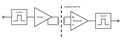 Block diagram of a transformer-isolated amplifier
 -
 Sample schematic of an optically isolated amplifier
 -
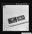 Optically isolated hybrid amplifier circuit (by Burr-Brown Corporation) with the isolation gap visible in the opened circuit on the right
 -
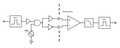 Block diagram of an isolation amplifier coupled with capacitors


Isolation amplifier usage
Isolation amplifiers are used to allow measurement of small signals in the presence of a high common mode voltage. The capacity of an isolation amplifier is a function of two key isolation amplifier specifications:
- The amplifier’s isolation breakdown voltage, which defines the absolute maximum common mode voltage that it will tolerate without damage. Specifications of 1,000 volts and more are common.
- The amplifier’s common mode rejection ratio (CMRR). The CMRR specification defines the degree to which the common mode voltage will disrupt the normal mode component measurement, and therefore affect measurement accuracy.
The frequency of the common mode voltage can adversely affect performance. Higher frequency common mode voltages create difficulty for many isolation amplifiers due to the parasitic capacitance of the isolation barrier. This capacitance appears as a low impedance to higher frequency signals, and allows the common mode voltage to essentially blow past the barrier and interfere with measurements, or even damage the amplifier. However, most common mode voltages are a composite of line voltages, so frequencies generally remain in the 50 to 60 Hz region with some harmonic content, well within the rejection range of most isolation amplifiers.
Differential amplifiers
A non-isolated differential amplifier does not provide isolation between input and output circuits. They share a power supply and a DC path can exist between input and output. A non-isolated differential amplifier can only withstand common-mode voltages up to the power supply voltage.
Similar to the instrumentation amplifier, isolation amplifiers have fixed differential gain over a wide range of frequencies, high input impedance and low output impedance.
Amplifier selection guidelines
Instrumentation amplifiers can be classified into four broad categories, organized from least to most costly:
- Single-ended. An unbalanced input, non-isolated. Suitable for measurements where common mode voltages are zero, or extremely small. Very inexpensive.
- Differential. A balanced input, non-isolated. Suitable for measurements where the sum of common mode and normal mode voltages remains within the measurement range of the amplifier.
- Single-ended, floating common. An isolated and quasi-balanced input (the floating common is typically connected to the (-) input of a differential amplifier). Suitable for off-ground measurements up to the breakdown voltage of the isolation barrier, and exhibits very good common mode rejection (100 db typical).
- Differential, floating common. An isolated and balanced input. Suitable for off-ground measurements to the breakdown voltage of the isolation barrier, and exhibits superb common mode rejection (>120 db).
For most industrial applications that require isolation, the single-ended floating design provides the best price/performance.
There are also two broad classifications of isolation amplifiers that should be considered in tandem with the application:
- Amplifiers providing input-to-output isolation without channel-to-channel isolation. This is a less expensive form of isolation that offers only one isolation barrier for a multi-channel instrument. Although the commons of each channel are isolated from power ground by the input-to-output isolation barrier, they are not isolated from each other. Therefore a common mode voltage on one will attempt to float all the others, sometimes with disastrous results. This form of isolation is suitable only when it is certain that there is only one common mode voltage that is equally applied to all channels.
- Amplifiers providing both input-to-output and channel-to-channel isolation. This is the purest form of isolation, and the option that should be considered for nearly all applications. Multi-channel instruments that employ it are immune to inconsistent common mode voltages on any combination of channels within the limits of the amplifiers.
Typical application
Stacked voltage cell measurements

Stacked voltage cell measurements are common with the growing popularity of solar cells and fuel cells. In this application the technician wants to profile the performance of individual series-connected voltages cells, but the need for an isolated amplifier is often overlooked. Each voltage cell (the normal mode voltage) is removed from ground by an amount equal to the sum of the voltage cells below it (the common mode voltage). Unless the amplifiers used to measure individual cell voltages are allowed to float at a level equal to the common mode voltage, measurements are not likely to be accurate for any but the first cell in the string where the common mode voltage is zero.
A non-isolated differential amplifier can be used but it will have a rated maximum common mode voltage that cannot be exceeded while maintaining accuracy.
References
- ↑ 1.0 1.1 1.2 Paul Horowitz, Winfield Hill The Art of Electronics Second Edition, Cambridge, 1989 ISBN 0-521-37095-7 pages 462-464
External links
 |  |
