Engineering:Pintle injector

The pintle injector is a type of propellant injector for a bipropellant rocket engine. Like any other injector, its purpose is to ensure appropriate flow rate and intermixing of the propellants as they are forcibly injected under high pressure into the combustion chamber, so that an efficient and controlled combustion process can happen.[1]
A pintle-based rocket engine can have a greater throttling range than one based on regular injectors, and will very rarely present acoustic combustion instabilities, because a pintle injector tends to create a self-stabilizing flow pattern.[2][3] Therefore, pintle-based engines are specially suitable for applications that require deep, fast, and safe throttling, such as landers.[4]
Pintle injectors began as early laboratory experimental apparatuses, used by Caltech's Jet Propulsion Laboratory in the mid-1950s, to study the mixing and combustion reaction times of hypergolic liquid propellants. The pintle injector was reduced to practice and developed by Space Technology Laboratories (STL), then a division of Ramo-Wooldridge Corp., later TRW, starting in 1960.[2]
There have been pintle-based engines built ranging from a few newtons of thrust up to several millions, and the pintle design has been tested with all the common and many exotic propellant combinations, including gelled propellants.[2] Pintle-based engines were first used on a crewed spacecraft during the Apollo Program in the Lunar Excursion Module's Descent Propulsion System,[4][2][5] however, it was not until October 1972 that the design was made public.[2][3] and U.S. Patent 3,699,772 was granted to its inventor Gerard W. Elverum Jr.[6]
Description
Working principle

A pintle injector is a type of coaxial injector. It consists of two concentric tubes and a central protrusion. Propellant A (usually the oxidizer, represented with blue in the image) flows through an outer tube, coming out as a cylindrical stream, while propellant B (usually the fuel, represented with red in the image) flows within an inner tube and impinges on a central pintle-shaped protrusion, (similar in shape to a poppet valve like those found on four-stroke engines), spraying out in a broad cone or a flat sheet that intersects the cylindrical stream of propellant A.[2][3]
In the typical pintle-based engine design, only a single central injector is used, differing from "showerhead" injector plates which use multiple parallel injector ports.[2]
Throttleability can be obtained either by placing valves before the injector, by moving the inner pintle or outer sleeve, or both.[2]
Many people have experienced throttleable pintle sprayers in the form of standard garden hose-end sprayers.[5]

Variants
In pintle engines that do not require throttling, the pintle is fixed in place, and propellant valves for startup and shutdown are placed somewhere else.[2]
A movable pintle allows for throttleability, and, if the moving part is the sleeve, the pintle itself can act as the propellant valve. This is called a Face Shutoff pintle. A fast-moving sleeve allows for the engine to be operated in pulses, and this is usually done in pintle-based RCS thrusters and missile divert thrusters.[2]
In a variant of the Face Shutoff pintle, the pintle itself is hydraulically actuated by the fuel via a pilot valve, and no extra valves are required between the engine and tanks. This is called an FSO (Face Shutoff Only) pintle.[2]
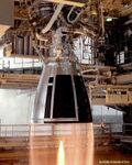
In some variants the pintle has grooves or orifices cut into it to produce radial jets in the flow of propellant B, this allows for extra unburned fuel to impinge on the walls of the combustion chamber, and provide fuel film cooling.[2][7] The pintle pictured here is of this type.

Advantages and disadvantages
Advantages
Compared to some injector designs, pintle injectors allow greater throttling of bipropellant flow rates, although throttling rocket engines in general is still very difficult. If only one central injector is used, the mass flow inside the combustion chamber will have two main recirculation zones which decrease acoustic instability without necessarily requiring acoustic cavities or baffles.[2][3]
The pintle injector design can deliver high combustion efficiency (typically 96–99%).[2][3]

If fuel is chosen for the inner flow (which is the case in most pintle-based engines), the injector can be tuned so that any excess fuel which is not reacted immediately as it passes through the oxidizer stream is projected onto the combustion chamber walls and cools them through evaporation, thus providing fuel film cooling to the combustion chamber walls, without incurring the mass penalty of a dedicated coolant subsystem.[2][7]
While pintle injectors have been developed for applications in rocket propulsion, due to their relative simplicity, they could easily be adapted for industrial fluid handling processes requiring high flowrate and thorough mixing.[8]
A given injector's performance can be easily optimized by varying the geometries of the outer propellant's annular gap and the central propellant slots (and/or continuous gap, if used). As this requires only two new pieces to be made, trying variations is usually cheaper and less time-consuming than with regular injectors.[2][3]
Disadvantages
Because combustion tends to occur in the surface of a frustum, peak thermal stresses are localized on the combustion chamber wall rather than a more evenly distributed combustion across the chamber section and more even heating. This has to be contemplated when designing the cooling system, or it might cause burn-through.[5][7][9]
The pintle injector is known to have caused throat-erosion problems in the early ablatively cooled Merlin engines due to uneven mixing causing hot streaks in the flow, however, as of 2021, it is not clear whether this is a problem that applies to all pintle-based engines, or this was a design problem of the Merlin.[7][10]
Pintle injectors work very well with liquid propellants and can be made to work with gelled propellants, but for gas–liquid or gas–gas applications, conventional injectors remain superior in performance.[9]
The pintle injector is desirable for engines that have to be throttled or restarted repeatedly, but it does not deliver optimal efficiency for fuel and oxidizer mixing at any given throttle rate.[9]

History
1950s
In 1957, Gerard W. Elverum Jr. was employed by the Jet Propulsion Laboratory, and working under the supervision of Art Grant to characterize the reaction rates of new rocket propellants by using a device consisting of two concentric tubes, through which propellants were fed at a known flowrate, and a set of thermocouples to measure their reaction rates. The device encountered problems, because as the propellants were flowing parallel to each other, not much mixing was happening. Elverum then placed a tip at the end of the innermost tube, attached to an internal support, which forced the inner propellant to flow outwards and mix with the outer propellant. This device worked fine for low energy propellants, but when high energy combinations started being tested, it proved impractical due to nearly instantaneous reaction times at the mixing point. In order to keep the device from blowing itself apart during high energy tests, the outer tube was retracted, thus constituting a primitive pintle injector.[2]
Peter Staudhammer, under the supervision of Program Manager Elverum, had a technician cut multiple slots across the end of an available inner tube and subsequent tests of this new configuration showed a substantial improvement in mixing efficiency.[2][3]

1960s
By 1960, Elverum, Grant, and Staudhammer had moved to the newly-formed Space Technology Laboratories, Inc. (Later TRW, Inc.) to pursue development of monopropellant and bipropellant rocket engines. By 1961, the pintle injector was developed into a design usable in rocket engines, and subsequently, the pintle injector design was matured and developed by a number of TRW employees, adding such features as throttling, rapid pulsing capability, and face shutoff.[2]
Throttling was tested in the 1961 MIRA 500, at 25 to 500 lbf (111 to 2,224 N) and its 1962 successor, the MIRA 5000, at 250 to 5,000 lbf (1,112 to 22,241 N).[2]
In 1963, TRW introduced the MIRA 150A as a backup for the Thiokol TD-339 vernier thruster to be used in the Surveyor probes, and started development of the Apollo Lunar Excursion Module's Descent Propulsion System. Near this time, a pintle injector was considered for simplicity and lower cost on the Sea Dragon.[2]
In parallel with those projects, TRW continued development of other pintle engines, including by 1966 the URSA (Universal Rocket for Space Applications) series. These were bipropellant engines offered at fixed thrusts of 25, 100, or 200 lbf, (111, 445, or 890 N) with options for either ablative or radiatively cooled combustion chambers. These engines were capable of pulsing at 35 Hz, with pulse widths as small as .02 seconds, but also had design steady state firing life in excess of 10,000 seconds (with radiatively-cooled chambers).[2]
In 1967 the Apollo Descent Propulsion System was qualified for flight.[2]
From 1968 to 1970, a 250,000 lbf (1,112,055 N) engine was tested.[2]
1970s
In 1972 the Apollo Descent Propulsion System ended production, but starting in 1974, and continuing through 1988, the TR-201, a simplified, low cost derivative of it, featuring ablative cooling and fixed thrust, was used in the second stage of the Delta 2914 and 3914 launch vehicles.[2]
In October 1972, the pintle injector design was patented and made public.[2]
1980s
In the early 1980s, a series of design refinements were applied to the pintle injector obtaining exceptionally fast and repeatable pulses on command and linear throttling capability. By enabling shutoff of propellants at their injection point into the combustion chamber, the pintle injector provided excellent pulse response by eliminating injector "dribble volume" effects.[2]
Starting in 1981, a very compact, 8,200 lbf N2O4/MMH engine employing this feature was developed as a pitch and yaw thruster for the army's SENTRY missile program. This engine could throttle over a 19:1 thrust range and deliver repeatable "on" pulses as small as 8 milliseconds at any thrust level.[2]
A further refinement of the face shutoff injector was used on the Army Strategic Defense Command's Exoatmospheric Reentry-vehicle Interceptor Subsystem (ERIS). In its 900 lbf lateral divert engines the injector shutoff element provided the only control of propellant flow. The large bipropellant valve normally required in such engines was replaced by a small pilot valve that used high pressure fuel (MMH) to hydraulically actuate the moveable injector sleeve. This feature, called FSO (Face Shutoff Only) greatly improved overall thruster response and significantly reduced engine size and mass.[2]
Another design challenge from the mid 1980s and early 1990s was that of obtaining miniaturization of rocket engines. As part of the Air Force Brilliant Pebbles program, TRW developed a very small 5 lbf (22 N) N2O4/hydrazine thruster using a pintle injector. This radiatively-cooled engine weighed 0.3 lb (135 grams) and was successfully tested in August 1993, delivering over 300 seconds Isp with a 150:1 nozzle expansion ratio. The pintle diameter was (1.6764 mm) and scanning electron microscopy was needed to verify the dimensions on the ± (0.0762 mm ±0.00762 mm) radial metering orifices.[2]
1990s
The preceding technology innovations enabled the first exoatmospheric kinetic kill of a simulated reentry warhead off Kwajalein atoll on 28 January 1991 on the first flight of ERIS.[2]
In the late '90s, FSO pintle injectors were used with gelled propellants, which have a normal consistency like that of smooth peanut butter. Gelled propellants typically use either aluminum powder or carbon powder to increase the energy density of the liquid fuel base (typically MMH) and they use additives to rheologically match the oxidizer (typically IRFNA based) to the fuel. For gelled propellants to be used on a rocket, face shutoff is mandatory to prevent dry-out of the base liquid during off times between pulses, which would otherwise result in the solids within the gels plugging the injector passages. FSO pintle injectors were used on a variety of programs, the McDonnell Douglas Advanced Crew Escape Seat – Experimental (ACES-X) program and its successor, the Gel Escape System Propulsion (GESP) program.[2]
Another major design adaptation in this time period was the use of pintle injectors with cryogenic liquid hydrogen fuel. Beginning in 1991, TRW joined with McDonnell Douglas and NASA Lewis (now Glenn) Research Center to demonstrate that TRW's pintle engine could use direct injection of liquid hydrogen to simplify the design of high-performance booster engines. Attempts to use direct injection of cryogenic hydrogen in other types of injectors had until then consistently resulted in the onset of combustion instabilities.[2]
In late 1991 and early 1992, a 16,000 lbf (71,172 N) LOX/LH2 test engine was successfully operated with direct injection of liquid hydrogen and liquid oxygen propellants. A total of 67 firings were conducted, and the engine demonstrated excellent performance and total absence of combustion instabilities. Subsequently, this same test engine was adapted for and was successfully tested with LOX/LH2 at 40,000 lbf (177,929 N) and with LOX/RP-1 at 13,000 and 40,000 lbf. (57,827 and 177,929 N).[2]
At the same time, TR-306 liquid apogee engines were used on the Anik E-1/E-2 and Intelsat K spacecraft.[2]
In August 1999 the dual mode TR-308 was used to place NASA's Chandra spacecraft on its final orbit.[2]
The early FSO injector and gel propellant development work of the late 1980s and early 1990s led to the world's first missile flights using gelled oxidizer and gelled fuel propellants on the Army's/AMCOM's Future Missile Technology Integration (FMTI) program, with the first flight in March 1999 and the second flight in May 2000.[2]
2000s
In the early 2000s TRW continued development of large LOX/LH2 pintle engines, and test-fired the TR-106 at NASA's John C. Stennis Space Center. This was a 650,000 lbf (2,892,000 N) engine, a 16:1 scale-up from the largest previous LOX/LH2 pintle engine and about a 3:1 scale-up from the largest previous pintle engine ever tested. This injector's pintle diameter was 22 inches (56 cm), by far the largest built to date.[5]
In 2002 the larger TR-107 was designed.[11]
Tom Mueller, who had worked on the TR-106 and TR-107, was hired by SpaceX and started development of the Merlin and Kestrel engines.[12][13]
2010s
The Merlin engine was the only pintle injector engine in operation, used for all SpaceX Falcon 9 and Falcon Heavy flights.[14]
2020s
In the early 2020s, the Merlin engine continued to be used on the Falcon 9 and Falcon Heavy. The pintle injector was also used on the Reaver 1 engine by Firefly Aerospace.[15]
Engines known to use pintle injectors
| Name | Manufacturer | Fuel | Oxidizer | Thrust, N | Thrust, lbf |
|---|---|---|---|---|---|
| AC/LAE[2] | TRW Inc. | Hydrazine | N2O4 | 534 | 120 |
| Apollo Common RCS Engine[2] | TRW Inc. | MMH | N2O4 | 445 | 100 |
| Boomie Zoomie[16] | Purdue SEDS | Liquid Methane | LOX | 2,384 | 536 |
| Boomie Zoomie B (BZB) | Purdue SEDS | Liquid Methane | LOX | 4,003 | 900 |
| Descent Propulsion System[2] | TRW Inc. | Aerozine 50 | N2O4 | 45,040 | 10,125 |
| DLX-150B Firebolt | Delft Aerospace Rocket Engineering | Ethanol 80%, water 20% | LOX | 9,000 | 2,000 |
| DM/LAE[2] | TRW Inc. | Hydrazine | N2O4 | 467 | 105 |
| ERIS Divert Thruster[2] | TRW Inc. | MMH | N2O4 | 4,048 | 910 |
| Executor[17] | ARCA | Kerosene | LOX | 260,000 | 57,300 |
| E-1 Lightbulb | Space Enterprise at Berkeley | Propane or Methane | LOX | 2700 | 605 |
| FMTI[2] | TRW Inc. | Gelled MMH with carbon additive | Gelled IRFNA (Inhibited red fuming nitric acid) | ||
| ISPS[2] | TRW Inc. | USO (UDMH + 0.9% Silicone oil) | HDA (Type 4 high density red fuming nitric acid) | 445 | 100 |
| Janus | ERAU Rocket Development Lab | Kerosene | LOX | 4,448 | 1000 |
| Kestrel | SpaceX | RP-1 | LOX | 31,000 | 6,900 |
| KEW 10.2 Divert Thruster[2] | TRW Inc. | MMH | N2O4 | 1,334 | 300 |
| Lunar Hopper Engine[2] | TRW Inc. | MMH | MON-10 | 800 | 180 |
| Merlin[14] | SpaceX | RP-1 | LOX | Several variants, see main article for details. | Several variants, see main article for details. |
| Mira 1[18] | Oregon State HALE | Jet-A | LOX | 6,005 | 1,350 |
| Mira 2[19] | Oregon State HALE | Jet-A | LOX | 7,717 | 1,600 |
| MIRA 150A[2] | TRW Inc. | MMH | MON-10 | 667 | 150 |
| MIRA 500[2] | TRW Inc. | Aerozine 50 or Hydrazine | N2O4 | 2,224 | 500 |
| MIRA 5000[2] | TRW Inc. | Aerozine 50 or UDMH | N2O4 or RFNA | 22,241 | 5,000 |
| MMBPS[2] | TRW Inc. | MMH | N2O4 | 391 | 88 |
| Morpheus[20] | Purdue University | Methane | LOX | 5,783-18,683 | 1,300-4,200 |
| Reaver 1[15] | Firefly Aerospace | RP-1 | LOX | 36,800 | 82,750 |
| SENTRY Jet Interaction Pitch and Yaw Thruster[2] | TRW Inc. | MMH | N2O4 | 36,475 | 8,200 |
| THANOS-A | Imperial College London Rocketry | Methanol | N2O | 3000 | 674 |
| THANOS-R | Imperial College London Rocketry | Methanol | N2O | 4000 | 899 |
| THANOS-R2 | Imperial College London Rocketry | Ethanol | N2O | 6000 | 1349 |
| TR-106[2] | TRW Inc. | LH2 | LOX | 2,892,000 | 650,000 |
| TR-107[11] | TRW Inc./Northrop Grumman | RP-1 | LOX | 4,900,000 | 1,100,000 |
| TR-201[2] | TRW Inc. | Aerozine 50 | N2O4 | 4,900 | 9,419 |
| TR-306[2] | TRW Inc. | Hydrazine | N2O4 | ||
| TR-308[2] | TRW Inc. | Hydrazine | N2O4 | ||
| TR-312[2] | TRW Inc. | Hydrazine or MMH | N2O4 | ||
| URSA 25 R[2] | TRW Inc. | Aerozine 50 or MMH | N2O4 | 111 | 25 |
| URSA 100 R[2] | TRW Inc. | Aerozine 50 or MMH | N2O4 | 445 | 100 |
| URSA 200 R[2] | TRW Inc. | Aerozine 50 or MMH | N2O4 | 890 | 200 |
| Valkyrie | KXR UCF | Ethanol | N2O | 890 | 200 |
| Welkin[21] | Galactic Energy | RP-1 | LOX | 500,000 | 110,000 |
| YJ-1S[22] | Yellow Jacket Space Program (YJSP) | Jet-A | LOX | 3,336 | 750 |
| Anathema | San Diego State University Rocket Project (SDSU RP) | Ethanol | LOX | 4,448 | 1000 |
| COSMOS[23] | Interstellar Technologies Inc. | LCH4 | LOX | 130,000[24] | 29226 |
| Elysium 1.1[25] | Texas A&M Rocket Engine Design (RED) | Ethanol 95%, Water 5% | N2O | 2,277.50 | 512 |
References
![]() This article incorporates public domain material from websites or documents of the National Aeronautics and Space Administration.
This article incorporates public domain material from websites or documents of the National Aeronautics and Space Administration.
- ↑ Krzycki, Leroy J. (1967). How to Design, Build and Test Small Liquid-Fuel Rocket Engines. United States of America: ROCKETLAB. pp. 23. https://archive.org/details/howtodesignbuild00krzy.
- ↑ 2.00 2.01 2.02 2.03 2.04 2.05 2.06 2.07 2.08 2.09 2.10 2.11 2.12 2.13 2.14 2.15 2.16 2.17 2.18 2.19 2.20 2.21 2.22 2.23 2.24 2.25 2.26 2.27 2.28 2.29 2.30 2.31 2.32 2.33 2.34 2.35 2.36 2.37 2.38 2.39 2.40 2.41 2.42 2.43 2.44 2.45 2.46 2.47 2.48 2.49 2.50 2.51 2.52 2.53 2.54 2.55 2.56 2.57 2.58 Dressler, Gordon A.; Bauer, J. Martin (2000). "TRW Pintle Engine Heritage and Performance Characteristics". 36th AIAA/ASME/SAE/ASEE Joint Propulsion Conference and Exhibit, Joint Propulsion Conferences. AIAA. doi:10.2514/6.2000-3871. AIAA-2000-3871. http://www.rocket-propulsion.info/resources/articles/TRW_PINTLE_ENGINE.pdf. Retrieved 14 May 2017.
- ↑ 3.0 3.1 3.2 3.3 3.4 3.5 3.6 "Liquid propellant rocket engine coaxial injector" US patent 3699772
- ↑ 4.0 4.1 William R. Hammock, Jr.; Eldon C. Currie (March 1973). "Apollo Experience Report - Descent Propulsion System". https://ntrs.nasa.gov/archive/nasa/casi.ntrs.nasa.gov/19730011150.pdf.
- ↑ 5.0 5.1 5.2 5.3 Fischer, Dave. "Pintle Injector Rocket Engines". National Space Society Blog. National Space Society. http://blog.nss.org/?p=1900.
- ↑ , Gerard W."Variable thrust bipropellant rocket engine" US patent 3205656, issued 1963-02-25
- ↑ 7.0 7.1 7.2 7.3 "Some SpaceX Commentary | Selenian Boondocks" (in en-US). https://selenianboondocks.com/2006/01/some-spacex-commentary/.
- ↑ Heister, S.D. (25 February 2011). "Chapter 28: Pintle Injectors". in Ashgriz, Nasser (in en). Handbook of Atomization and Sprays: Theory and Applications (2011 ed.). New York: Springer. pp. 647–655. doi:10.1007/978-1-4419-7264-4_28. ISBN 978-1-4419-7263-7. https://archive.org/details/handbookatomizat00ashg.
- ↑ 9.0 9.1 9.2 "Thread: So why haven't pintle injector rockets taken over the world?". https://boards.straightdope.com/sdmb/showpost.php?s=d7479e9527e27f3d9f64662c3ca3536f&p=17848857&postcount=5.
- ↑ Musk, Elon [@elonmusk] (2019-02-21). "Pinter injector tends to have hot & cold streaks. Hot streaks burn a rut at the throat that accelerates erosion." (in en). https://twitter.com/elonmusk/status/1098644877259096064.
- ↑ 11.0 11.1 "TR107 Engine Component Technologies". NASA Marshall Space Flight Center. November 2003. http://www.nasa.gov/centers/marshall/pdf/100428main_tr107.pdf.
- ↑ Seedhouse, Erik (2013). SpaceX: Making Commercial Spaceflight a Reality. Springer Praxis Books. ISBN 9781461455141.
- ↑ Lord, M.G. (1 October 2007). "Rocket Man". L.A. Mag. http://www.lamag.com/features/2007/10/1/rocket-man/print.
- ↑ 14.0 14.1 "Falcon 9 User's Guide". https://www.spacex.com/sites/spacex/files/falcon_users_guide_02182019.pdf.
- ↑ 15.0 15.1 (in en) Tour Firefly Aerospace's Factory and Test Site With Their CEO, Tom Markusic, 11 October 2021, https://www.youtube.com/watch?v=ac-V8mO0lWo, retrieved 2021-10-12
- ↑ Meriam, Silas; Nilsen, Christopher; Tanner, Matthew; Runkle, Kyle; Jacob, Bartkiewicz; Groome, Robert; Meyer, Scott E. (2019-08-16), "Student Development of a Liquid Oxygen, Liquid Methane Sounding Rocket and Launch Infrastructure", AIAA Propulsion and Energy 2019 Forum, AIAA Propulsion and Energy Forum (American Institute of Aeronautics and Astronautics), doi:10.2514/6.2019-3934, ISBN 978-1-62410-590-6, https://arc.aiaa.org/doi/10.2514/6.2019-3934, retrieved 2019-08-28
- ↑ "Executor Rocket Engine". ARCA. http://www.arcaspace.com/en/executor.htm.
- ↑ "HALE" (in en-US). https://osuaiaa.com/hale.
- ↑ "HALE" (in en-US). https://osuaiaa.com/hale.
- ↑ Bedard, Michael; Feldman, Thomas; Rettenmaier, Andrew; Anderson, William (2012-07-30). "Student Design/Build/Test of a Throttleable LOX-LCH4 Thrust Chamber". 48th AIAA/ASME/SAE/ASEE Joint Propulsion Conference & Exhibit (Reston, Virginia: American Institute of Aeronautics and Astronautics). doi:10.2514/6.2012-3883. ISBN 978-1-60086-935-8. http://dx.doi.org/10.2514/6.2012-3883.
- ↑ "GALACTIC ENERGY". https://www.galactic-energy.cn/index.php/En/List/cid/18.
- ↑ (in en) Hot-Fire Test is a Success for Yellow Jacket Space Program, https://ae.gatech.edu/news/2019/12/hot-fire-test-success-yellow-jacket-space-program, retrieved 2022-11-09
- ↑ "ZERO Payload User's Guide". July 2024. https://www.istellartech.com/7hbym/wp-content/themes/ist_2023/assets/pdf/usersguide_zero.pdf.
- ↑ "ZERO (ロケット)" (in ja), Wikipedia, 2024-01-21, https://ja.wikipedia.org/wiki/ZERO_(%E3%83%AD%E3%82%B1%E3%83%83%E3%83%88), retrieved 2024-10-18
- ↑ "Elysium 1.1" (in en-US). https://www.tamured.space/projects/elysium-1-1.
| Liquid fuel |
|  | ||||||||||
|---|---|---|---|---|---|---|---|---|---|---|---|---|
| Solid fuel |
| |||||||||||
| ||||||||||||
 |  |
