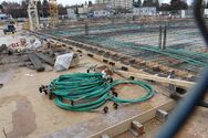
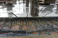
Engineering:Prestressed concrete
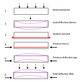
- Non-prestressed beam without load
- Non-prestressed beam with load
- Before concrete solidifies, tendons embedded in concrete are tensioned
- After concrete solidifies, tendons apply compressive stress to concrete
- Prestressed beam without load
- Prestressed beam with load
Prestressed concrete is a form of concrete used in construction. It is substantially "prestressed" (compressed) during production, in a manner that strengthens it against tensile forces which will exist when in service.[1][2]:3–5[3]
This compression is produced by the tensioning of high-strength "tendons" located within or adjacent to the concrete and is done to improve the performance of the concrete in service.[4] Tendons may consist of single wires, multi-wire strands or threaded bars that are most commonly made from high-tensile steels, carbon fiber or aramid fiber.[1]:52–59 The essence of prestressed concrete is that once the initial compression has been applied, the resulting material has the characteristics of high-strength concrete when subject to any subsequent compression forces and of ductile high-strength steel when subject to tension forces. This can result in improved structural capacity and/or serviceability compared with conventionally reinforced concrete in many situations.[5][2]:6 In a prestressed concrete member, the internal stresses are introduced in a planned manner so that the stresses resulting from the imposed loads are counteracted to the desired degree.
Prestressed concrete is used in a wide range of building and civil structures where its improved performance can allow for longer spans, reduced structural thicknesses, and material savings compared with simple reinforced concrete. Typical applications include high-rise buildings, residential slabs, foundation systems, bridge and dam structures, silos and tanks, industrial pavements and nuclear containment structures.[6]
First used in the late-nineteenth century,[1] prestressed concrete has developed beyond pre-tensioning to include post-tensioning, which occurs after the concrete is cast. Tensioning systems may be classed as either monostrand, where each tendon's strand or wire is stressed individually, or multi-strand, where all strands or wires in a tendon are stressed simultaneously.[5] Tendons may be located either within the concrete volume (internal prestressing) or wholly outside of it (external prestressing). While pre-tensioned concrete uses tendons directly bonded to the concrete, post-tensioned concrete can use either bonded or unbonded tendons.
Pre-tensioned concrete
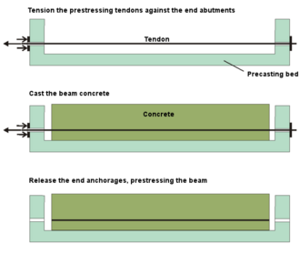
Pre-tensioned concrete is a variant of prestressed concrete where the tendons are tensioned prior to the concrete being cast.[1]:25 The concrete bonds to the tendons as it cures, following which the end-anchoring of the tendons is released, and the tendon tension forces are transferred to the concrete as compression by static friction.[5]:7
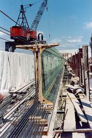
Pre-tensioning is a common prefabrication technique, where the resulting concrete element is manufactured off-site from the final structure location and transported to site once cured. It requires strong, stable end-anchorage points between which the tendons are stretched. These anchorages form the ends of a "casting bed" which may be many times the length of the concrete element being fabricated. This allows multiple elements to be constructed end-to-end in the one pre-tensioning operation, allowing significant productivity benefits and economies of scale to be realized.[5][7]
The amount of bond (or adhesion) achievable between the freshly set concrete and the surface of the tendons is critical to the pre-tensioning process, as it determines when the tendon anchorages can be safely released. Higher bond strength in early-age concrete will speed production and allow more economical fabrication. To promote this, pre-tensioned tendons are usually composed of isolated single wires or strands, which provides a greater surface area for bonding than bundled-strand tendons.[5]
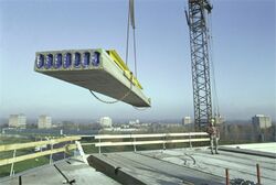
Unlike those of post-tensioned concrete (see below), the tendons of pre-tensioned concrete elements generally form straight lines between end-anchorages. Where "profiled" or "harped" tendons[8] are required, one or more intermediate deviators are located between the ends of the tendon to hold the tendon to the desired non-linear alignment during tensioning.[1]:68–73[5]:11 Such deviators usually act against substantial forces, and hence require a robust casting-bed foundation system. Straight tendons are typically used in "linear" precast elements, such as shallow beams, hollow-core planks and slabs; whereas profiled tendons are more commonly found in deeper precast bridge beams and girders.
Pre-tensioned concrete is most commonly used for the fabrication of structural beams, floor slabs, hollow-core planks, balconies, lintels, driven piles, water tanks and concrete pipes.
Post-tensioned concrete
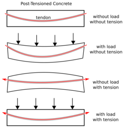
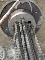
Post-tensioned concrete is a variant of prestressed concrete where the tendons are tensioned after the surrounding concrete structure has been cast.[1]:25
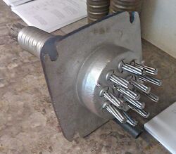
The tendons are not placed in direct contact with the concrete, but are encapsulated within a protective sleeve or duct which is either cast into the concrete structure or placed adjacent to it. At each end of a tendon is an anchorage assembly firmly fixed to the surrounding concrete. Once the concrete has been cast and set, the tendons are tensioned ("stressed") by pulling the tendon ends through the anchorages while pressing against the concrete. The large forces required to tension the tendons result in a significant permanent compression being applied to the concrete once the tendon is "locked-off" at the anchorage.[1]:25[5]:7 The method of locking the tendon-ends to the anchorage is dependent upon the tendon composition, with the most common systems being "button-head" anchoring (for wire tendons), split-wedge anchoring (for strand tendons), and threaded anchoring (for bar tendons).[1]:79–84
Tendon encapsulation systems are constructed from plastic or galvanised steel materials, and are classified into two main types: those where the tendon element is subsequently bonded to the surrounding concrete by internal grouting of the duct after stressing (bonded post-tensioning); and those where the tendon element is permanently debonded from the surrounding concrete, usually by means of a greased sheath over the tendon strands (unbonded post-tensioning).[1]:26[5]:10
Casting the tendon ducts/sleeves into the concrete before any tensioning occurs allows them to be readily "profiled" to any desired shape including incorporating vertical and/or horizontal curvature. When the tendons are tensioned, this profiling results in reaction forces being imparted onto the hardened concrete, and these can be beneficially used to counter any loadings subsequently applied to the structure.[2]:5–6[5]:48:9–10
Bonded post-tensioning
In bonded post-tensioning, tendons are permanently bonded to the surrounding concrete by the in situ grouting of their encapsulating ducting (after tendon tensioning). This grouting is undertaken for three main purposes: to protect the tendons against corrosion; to permanently "lock-in" the tendon pre-tension, thereby removing the long-term reliance upon the end-anchorage systems; and to improve certain structural behaviors of the final concrete structure.[9]
Bonded post-tensioning characteristically uses tendons each comprising bundles of elements (e.g., strands or wires) placed inside a single tendon duct, with the exception of bars which are mostly used unbundled. This bundling makes for more efficient tendon installation and grouting processes, since each complete tendon requires only one set of end-anchorages and one grouting operation. Ducting is fabricated from a durable and corrosion-resistant material such as plastic (e.g., polyethylene) or galvanised steel, and can be either round or rectangular/oval in cross-section.[2]:7 The tendon sizes used are highly dependent upon the application, ranging from building works typically using between 2 and 6 strands per tendon, to specialized dam works using up to 91 strands per tendon.
Fabrication of bonded tendons is generally undertaken on-site, commencing with the fitting of end-anchorages to formwork, placing the tendon ducting to the required curvature profiles, and reeving (or threading) the strands or wires through the ducting. Following concreting and tensioning, the ducts are pressure-grouted and the tendon stressing-ends sealed against corrosion.[5]:2
Unbonded post-tensioning
Unbonded post-tensioning differs from bonded post-tensioning by allowing the tendons permanent freedom of longitudinal movement relative to the concrete. This is most commonly achieved by encasing each individual tendon element within a plastic sheathing filled with a corrosion-inhibiting grease, usually lithium based. Anchorages at each end of the tendon transfer the tensioning force to the concrete, and are required to reliably perform this role for the life of the structure.[9]:1
Unbonded post-tensioning can take the form of:
- Individual strand tendons placed directly into the concreted structure (e.g., buildings, ground slabs)
- Bundled strands, individually greased-and-sheathed, forming a single tendon within an encapsulating duct that is placed either within or adjacent to the concrete (e.g., restressable anchors, external post-tensioning)
For individual strand tendons, no additional tendon ducting is used and no post-stressing grouting operation is required, unlike for bonded post-tensioning. Permanent corrosion protection of the strands is provided by the combined layers of grease, plastic sheathing, and surrounding concrete. Where strands are bundled to form a single unbonded tendon, an enveloping duct of plastic or galvanised steel is used and its interior free-spaces grouted after stressing. In this way, additional corrosion protection is provided via the grease, plastic sheathing, grout, external sheathing, and surrounding concrete layers.[9]:1
Individually greased-and-sheathed tendons are usually fabricated off-site by an extrusion process. The bare steel strand is fed into a greasing chamber and then passed to an extrusion unit where molten plastic forms a continuous outer coating. Finished strands can be cut-to-length and fitted with "dead-end" anchor assemblies as required for the project.
Comparison between bonded and unbonded post-tensioning
Both bonded and unbonded post-tensioning technologies are widely used around the world, and the choice of system is often dictated by regional preferences, contractor experience, or the availability of alternative systems. Either one is capable of delivering code-compliant, durable structures meeting the structural strength and serviceability requirements of the designer.[9]:2
The benefits that bonded post-tensioning can offer over unbonded systems are:
- Reduced reliance on end-anchorage integrity
Following tensioning and grouting, bonded tendons are connected to the surrounding concrete along their full length by high-strength grout. Once cured, this grout can transfer the full tendon tension force to the concrete within a very short distance (approximately 1 metre). As a result, any inadvertent severing of the tendon or failure of an end anchorage has only a very localised impact on tendon performance, and almost never results in tendon ejection from the anchorage.[2]:18[9]:7 - Increased ultimate strength in flexure
With bonded post-tensioning, any flexure of the structure is directly resisted by tendon strains at that same location (i.e. no strain re-distribution occurs). This results in significantly higher tensile strains in the tendons than if they were unbonded, allowing their full yield strength to be realised, and producing a higher ultimate load capacity.[2]:16–17[5]:10 - Improved crack-control
In the presence of concrete cracking, bonded tendons respond similarly to conventional reinforcement (rebar). With the tendons fixed to the concrete at each side of the crack, greater resistance to crack expansion is offered than with unbonded tendons, allowing many design codes to specify reduced reinforcement requirements for bonded post-tensioning.[9]:4[10]:1 - Improved fire performance
The absence of strain redistribution in bonded tendons may limit the impact that any localised overheating has on the overall structure. As a result, bonded structures may display a higher capacity to resist fire conditions than unbonded ones.[11]
The benefits that unbonded post-tensioning can offer over bonded systems are:
- Ability to be prefabricated
Unbonded tendons can be readily prefabricated off-site complete with end-anchorages, facilitating faster installation during construction. Additional lead time may need to be allowed for this fabrication process. - Improved site productivity
The elimination of the post-stressing grouting process required in bonded structures improves the site-labour productivity of unbonded post-tensioning.[9]:5 - Improved installation flexibility
Unbonded single-strand tendons have greater handling flexibility than bonded ducting during installation, allowing them a greater ability to be deviated around service penetrations or obstructions.[9]:5 - Reduced concrete cover
Unbonded tendons may allow some reduction in concrete element thickness, as their smaller size and increased corrosion protection may allow them to be placed closer to the concrete surface.[2]:8 - Simpler replacement and/or adjustment
Being permanently isolated from the concrete, unbonded tendons are able to be readily de-stressed, re-stressed and/or replaced should they become damaged or need their force levels to be modified in-service.[9]:6 - Superior overload performance
Although having a lower ultimate strength than bonded tendons, unbonded tendons' ability to redistribute strains over their full length can give them superior pre-collapse ductility. In extremes, unbonded tendons can resort to a catenary-type action instead of pure flexure, allowing significantly greater deformation before structural failure.[12]
Tendon durability and corrosion protection
Long-term durability is an essential requirement for prestressed concrete given its widespread use. Research on the durability performance of in-service prestressed structures has been undertaken since the 1960s,[13] and anti-corrosion technologies for tendon protection have been continually improved since the earliest systems were developed.[14]
The durability of prestressed concrete is principally determined by the level of corrosion protection provided to any high-strength steel elements within the prestressing tendons. Also critical is the protection afforded to the end-anchorage assemblies of unbonded tendons or cable-stay systems, as the anchorages of both of these are required to retain the prestressing forces. Failure of any of these components can result in the release of prestressing forces, or the physical rupture of stressing tendons.
Modern prestressing systems deliver long-term durability by addressing the following areas:
- Tendon grouting (bonded tendons)
Bonded tendons consist of bundled strands placed inside ducts located within the surrounding concrete. To ensure full protection to the bundled strands, the ducts must be pressure-filled with a corrosion-inhibiting grout, without leaving any voids, following strand-tensioning. - Tendon coating (unbonded tendons)
Unbonded tendons comprise individual strands coated in an anti-corrosion grease or wax, and fitted with a durable plastic-based full-length sleeve or sheath. The sleeving is required to be undamaged over the tendon length, and it must extend fully into the anchorage fittings at each end of the tendon. - Double-layer encapsulation
Prestressing tendons requiring permanent monitoring and/or force adjustment, such as stay-cables and re-stressable dam anchors, will typically employ double-layer corrosion protection. Such tendons are composed of individual strands, grease-coated and sleeved, collected into a strand-bundle and placed inside encapsulating polyethylene outer ducting. The remaining void space within the duct is pressure-grouted, providing a multi-layer polythene-grout-plastic-grease protection barrier system for each strand. - Anchorage protection
In all post-tensioned installations, protection of the end-anchorages against corrosion is essential, and critically so for unbonded systems.
Several durability-related events are listed below:
- Ynys-y-Gwas bridge, West Glamorgan, Wales, 1985
A single-span, precast-segmental structure constructed in 1953 with longitudinal and transverse post-tensioning. Corrosion attacked the under-protected tendons where they crossed the in-situ joints between the segments, leading to sudden collapse.[14]:40 - Scheldt River bridge, Melle, Belgium, 1991
A three-span prestressed cantilever structure constructed in the 1950s. Inadequate concrete cover in the side abutments resulted in tie-down cable corrosion, leading to a progressive failure of the main bridge span and the death of one person.[15] - UK Highways Agency, 1992
Following discovery of tendon corrosion in several bridges in England, the Highways Agency issued a moratorium on the construction of new internally grouted post-tensioned bridges and embarked on a 5-year programme of inspections on its existing post-tensioned bridge stock. The moratorium was lifted in 1996.[16][17] - Pedestrian bridge, Charlotte Motor Speedway, North Carolina, US, 2000
A multi-span steel and concrete structure constructed in 1995. An unauthorised chemical was added to the tendon grout to speed construction, leading to corrosion of the prestressing strands and the sudden collapse of one span, injuring many spectators.[18] - Hammersmith Flyover London, England, 2011
Sixteen-span prestressed structure constructed in 1961. Corrosion from road de-icing salts was detected in some of the prestressing tendons, necessitating initial closure of the road while additional investigations were done. Subsequent repairs and strengthening using external post-tensioning was carried out and completed in 2015.[19][20] - Petrulla Viaduct ("Viadotto Petrulla"), Sicily, Italy, 2014
One span of a 12-span viaduct collapsed on 7 July 2014, causing 4 injuries,[21] due to corrosion of the post-tensioning tendons. - Genoa bridge collapse, 2018. The Ponte Morandi was a cable-stayed bridge characterised by a prestressed concrete structure for the piers, pylons and deck, very few stays, as few as two per span, and a hybrid system for the stays constructed from steel cables with prestressed concrete shells poured on. The concrete was only prestressed to 10 MPa, resulting in it being prone to cracks and water intrusion, which caused corrosion of the embedded steel.
- Churchill Way flyovers, Liverpool, England
The flyovers were closed in September 2018 after inspections revealed poor quality concrete, tendon corrosion and signs of structural distress. They were demolished in 2019.[22]
Applications
Prestressed concrete is a highly versatile construction material as a result of it being an almost ideal combination of its two main constituents: high-strength steel, pre-stretched to allow its full strength to be easily realised; and modern concrete, pre-compressed to minimise cracking under tensile forces.[1]:12 Its wide range of application is reflected in its incorporation into the major design codes covering most areas of structural and civil engineering, including buildings, bridges, dams, foundations, pavements, piles, stadiums, silos, and tanks.[6]
Building structures
Building structures are typically required to satisfy a broad range of structural, aesthetic and economic requirements. Significant among these include: a minimum number of (intrusive) supporting walls or columns; low structural thickness (depth), allowing space for services, or for additional floors in high-rise construction; fast construction cycles, especially for multi-storey buildings; and a low cost-per-unit-area, to maximise the building owner's return on investment.
The prestressing of concrete allows "load-balancing" forces to be introduced into the structure to counter in-service loadings. This provides many benefits to building structures:
- Longer spans for the same structural depth
Load balancing results in lower in-service deflections, which allows spans to be increased (and the number of supports reduced) without adding to structural depth. - Reduced structural thickness
For a given span, lower in-service deflections allows thinner structural sections to be used, in turn resulting in lower floor-to-floor heights, or more room for building services. - Faster stripping time
Typically, prestressed concrete building elements are fully stressed and self-supporting within five days. At this point they can have their formwork stripped and re-deployed to the next section of the building, accelerating construction "cycle-times". - Reduced material costs
The combination of reduced structural thickness, reduced conventional reinforcement quantities, and fast construction often results in prestressed concrete showing significant cost benefits in building structures compared to alternative structural materials.
Some notable building structures constructed from prestressed concrete include: Sydney Opera House[23] and World Tower, Sydney;[24] St George Wharf Tower, London;[25] CN Tower, Toronto;[26] Kai Tak Cruise Terminal[27] and International Commerce Centre, Hong Kong;[28] Ocean Heights 2, Dubai;[29] Eureka Tower, Melbourne;[30] Torre Espacio, Madrid;[31] Guoco Tower (Tanjong Pagar Centre), Singapore;[32] Zagreb International Airport, Croatia;[33] and Capital Gate, Abu Dhabi UAE.[34]
-
ICC tower, Hong Kong
484m 2010 -
Guoco Tower, Singapore
290m 2016 -
Sydney Opera House
1973 -
Kai Tak Terminal
Hong Kong 2013 -
World Tower, Sydney
230m 2004 -
Ocean Heights 2, Dubai
335m 2016 -
Eureka Tower, Melbourne
297m 2006 -
Torre Espacio, Madrid
230m 2008 -
Capital Gate, Abu Dhabi
18° lean 2010
Civil structures
Bridges
Concrete is the most popular structural material for bridges, and prestressed concrete is frequently adopted.[35][36] When investigated in the 1940s for use on heavy-duty bridges, the advantages of this type of bridge over more traditional designs was that it is quicker to install, more economical and longer-lasting with the bridge being less lively.[37][38] One of the first bridges built in this way is the Adam Viaduct, a railway bridge constructed 1946 in the UK.[39] By the 1960s, prestressed concrete largely superseded reinforced concrete bridges in the UK, with box girders being the dominant form.[40]
In short-span bridges of around 10 to 40 metres (30 to 130 ft), prestressing is commonly employed in the form of precast pre-tensioned girders or planks.[41] Medium-length structures of around 40 to 200 metres (150 to 650 ft), typically use precast-segmental, in-situ balanced-cantilever and incrementally-launched designs.[42] For the longest bridges, prestressed concrete deck structures often form an integral part of cable-stayed designs.[43]
Dams
Concrete dams have used prestressing to counter uplift and increase their overall stability since the mid-1930s.[44][45] Prestressing is also frequently retro-fitted as part of dam remediation works, such as for structural strengthening, or when raising crest or spillway heights.[46][47]
Most commonly, dam prestressing takes the form of post-tensioned anchors drilled into the dam's concrete structure and/or the underlying rock strata. Such anchors typically comprise tendons of high-tensile bundled steel strands or individual threaded bars. Tendons are grouted to the concrete or rock at their far (internal) end, and have a significant "de-bonded" free-length at their external end which allows the tendon to stretch during tensioning. Tendons may be full-length bonded to the surrounding concrete or rock once tensioned, or (more commonly) have strands permanently encapsulated in corrosion-inhibiting grease over the free-length to permit long-term load monitoring and re-stressability.[48]
Silos and tanks
Circular storage structures such as silos and tanks can use prestressing forces to directly resist the outward pressures generated by stored liquids or bulk-solids. Horizontally curved tendons are installed within the concrete wall to form a series of hoops, spaced vertically up the structure. When tensioned, these tendons exert both axial (compressive) and radial (inward) forces onto the structure, which can directly oppose the subsequent storage loadings. If the magnitude of the prestress is designed to always exceed the tensile stresses produced by the loadings, a permanent residual compression will exist in the wall concrete, assisting in maintaining a watertight crack-free structure.[49][50][51]:61
Nuclear and blast
Prestressed concrete has been established as a reliable construction material for high-pressure containment structures such as nuclear reactor vessels and containment buildings, and petrochemical tank blast-containment walls. Using pre-stressing to place such structures into an initial state of bi-axial or tri-axial compression increases their resistance to concrete cracking and leakage, while providing a proof-loaded, redundant and monitorable pressure-containment system.[52][53][54]:585–594
Nuclear reactor and containment vessels will commonly employ separate sets of post-tensioned tendons curved horizontally or vertically to completely envelop the reactor core. Blast containment walls, such as for liquid natural gas (LNG) tanks, will normally utilize layers of horizontally-curved hoop tendons for containment in combination with vertically looped tendons for axial wall pre-stressing.
Hardstands and pavements
Heavily loaded concrete ground-slabs and pavements can be sensitive to cracking and subsequent traffic-driven deterioration. As a result, prestressed concrete is regularly used in such structures as its pre-compression provides the concrete with the ability to resist the crack-inducing tensile stresses generated by in-service loading. This crack-resistance also allows individual slab sections to be constructed in larger pours than for conventionally reinforced concrete, resulting in wider joint spacings, reduced jointing costs and less long-term joint maintenance issues.[54]:594–598[55] Initial works have also been successfully conducted on the use of precast prestressed concrete for road pavements, where the speed and quality of the construction has been noted as being beneficial for this technique.[56]
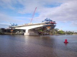
Some notable civil structures constructed using prestressed concrete include: Gateway Bridge, Brisbane Australia;[57] Incheon Bridge, South Korea;[58] Roseires Dam, Sudan;[59] Wanapum Dam, Washington, US;[60] LNG tanks, South Hook, Wales; Cement silos, Brevik Norway; Autobahn A73 bridge, Itz Valley, Germany; Ostankino Tower, Moscow, Russia; CN Tower, Toronto, Canada; and Ringhals nuclear reactor, Videbergshamn Sweden.[52]:37
-
Gateway Bridge
Brisbane, Aust. -
Incheon Bridge
South Korea -
Autobahn A73
Itz Valley, Germany -
Ostankino Tower
Moscow, Russia -
CN Tower
Toronto, Canada -
Norcem silos
Brevik, Norway -
Roseires Dam
Ad Damazin, Sudan -
Wanapum Dam
Washington, US -
LNG tanks
South Hook, Wales -
Ringhals nuclear plant
Videbergshamn, Sweden
Design agencies and regulations
Worldwide, many professional organizations exist to promote best practices in the design and construction of prestressed concrete structures. In the United States, such organizations include the Post-Tensioning Institute (PTI) and the Precast/Prestressed Concrete Institute (PCI).[61] Similar bodies include the Canadian Precast/Prestressed Concrete Institute (CPCI),[62] the UK's Post-Tensioning Association,[63] the Post Tensioning Institute of Australia[64] and the South African Post Tensioning Association.[65] Europe has similar country-based associations and institutions.
It is important to note that these organizations are not the authorities of building codes or standards, but rather exist to promote the understanding and development of prestressed concrete design, codes and best practices.
Rules and requirements for the detailing of reinforcement and prestressing tendons are specified by individual national codes and standards such as:
- European Standard EN 1992-2:2005 – Eurocode 2: Design of Concrete Structures;
- US Standard ACI318: Building Code Requirements for Reinforced Concrete; and
- Australian Standard AS 3600-2009: Concrete Structures.
See also
References
- ↑ 1.00 1.01 1.02 1.03 1.04 1.05 1.06 1.07 1.08 1.09 Lin, T.Y.; Burns, Ned H. (1981). Design of Prestressed Concrete Structures (Third ed.). New York, US: John Wiley & Sons. ISBN 0-471-01898-8. http://www.slideshare.net/ankitd1094/design-of-prestressed-concrete-structures-tylin-50801288. Retrieved 24 August 2016.
- ↑ 2.0 2.1 2.2 2.3 2.4 2.5 2.6 Federation Internationale du Beton (February 2005). fib Bulletin 31: Post-tensioning in Buildings. FIB. ISBN 978-2-88394-071-0. http://www.civil.ist.utl.pt/~cristina/EBAP/book_63505_fib31.pdf. Retrieved 26 August 2016.
- ↑ American Concrete Institute. "CT-13: ACI Concrete Terminology". Farmington Hills, Michigan US: ACI. https://www.concrete.org/topicsinconcrete/topicdetail/prestressed. Post-tensioned concreted is "structural concrete in which internal stresses have been introduced to reduce potential tensile stresses in the concrete resulting from loads."
- ↑ Warner, R. F.; Rangan, B. V.; Hall, A. S.; Faulkes, K. A. (1988). Concrete Structures. South Melbourne, Australia: Addison Welsley Longman. pp. 8–19. ISBN 0-582-80247-4.
- ↑ 5.00 5.01 5.02 5.03 5.04 5.05 5.06 5.07 5.08 5.09 5.10 Warner, R. F.; Faulkes, K. A. (1988). Prestressed Concrete (2nd ed.). Melbourne, Australia: Longman Cheshire. pp. 1–13. ISBN 0-582-71225-4.
- ↑ 6.0 6.1 Post-Tensioning Institute (2006). Post-Tensioning Manual (6th ed.). Phoenix, AZ US: PTI. pp. 5–54. ISBN 0-9778752-0-2. https://archive.org/details/posttensioningma00inst.
- ↑ Tokyo Rope Mfg Co Ltd. "CFCC Pre-tensioning Manual". http://www.maine.gov/mdot/contractors/projects/2014/019283.00-kittery/pm019283.00.pdf.
- ↑ "Tendons having one or more deviations from a straight line, either vertically or horizontally, between the ends of the structure"
- ↑ 9.0 9.1 9.2 9.3 9.4 9.5 9.6 9.7 9.8 Aalami, Bijan O. (5 September 1994). "Unbonded and bonded post-tensioning systems in building construction". PTI Technical Notes (Phoenix, Arizona US: Post-Tensioning Institute) (5). http://www.post-tensioning.org/Uploads/technote5.pdf. Retrieved 23 August 2016.
- ↑ Aalami, Bijan O. (February 2001). "Nonprestresed Bonded Reinforcement in Post-Tensioned Building Design". ADAPT Technical Publication (P2-01). http://www.adaptsoft.com/resources/ADAPT_P201_Nonpre-Bonded-PT-Bldg-Dsgnr.pdf. Retrieved 25 August 2016.
- ↑ Bailey, Colin G.; Ellobody, Ehab (2009). "Comparison of unbonded and bonded post-tensioned concrete slabs under fire conditions". The Structural Engineer 87 (19). https://www.istructe.org/journal/volumes/volume-87-(published-in-2009)/issues/issue-19/articles/comparison-of-unbonded-and-bonded-posttensioned-co. Retrieved 22 August 2016.
- ↑ Bondy, Kenneth B. (December 2012). "Two way post-tensioned slabs with bonded tendons". PTI Journal (US: Post-Tensioning Institute) 8 (2): 44. http://www.kenbondy.com/images/ProfessionalArticles/130129-Journal%20Reprint-Bondy-Two-Way%20PT%20Slabs%20with%20Bonded%20Tendons.pdf. Retrieved 25 August 2016.
- ↑ Szilard, Rudolph (October 1969). "Survey on the Durability of Prestressed Concrete Structures". PCI Journal: 62–73. http://www.pci.org/uploadedFiles/Siteroot/Publications/PCI_Journal/1969/DOI_Articles/jl-69-october-7.pdf. Retrieved 7 September 2016.
- ↑ 14.0 14.1 Podolny, Walter (September 1992). "Corrosion of Prestressing Steels and its Mitigation". PCI Journal 37 (5): 34–55. doi:10.15554/pcij.09011992.34.55. http://www.pci.org/uploadedFiles/Siteroot/Publications/PCI_Journal/1992/DOI_Articles/jl-92-september-october-4.pdf. Retrieved 7 September 2016.
- ↑ De Schutter, Geert (10 May 2012). Damage to Concrete Structures. CRC Press. pp. 31–33. ISBN 978-0-415-60388-1. https://books.google.com/books?id=38LLBQAAQBAJ&q=melle+bridge+belgium&pg=PA31. Retrieved 7 September 2016.
- ↑ Ryall, M. J.; Woodward, R.; Milne, D. (2000). Bridge Management 4: Inspection, Maintenance, Assessment and Repair. London: Thomas Telford. pp. 170–173. ISBN 978-0-7277-2854-8. https://books.google.com/books?id=vSZAnyWpzDcC&q=uk+highways+agency+moratorium+post-tensioning+bridges&pg=PA170. Retrieved 7 September 2016.
- ↑ CARES. "Post-Tensioning Systems". CARES. http://www.ukcares.com/certification/post-tensioning-systems.
- ↑ NACE. "Corrosdion Failures: Lowe's Motor Speedway Bridge Collapse". NACE. http://www.nace.org/CORROSION-FAILURES-Lowes-Motor-Speedway-Bridge-Collapse.aspx.
- ↑ Ed Davey and Rebecca Cafe (3 December 2012). "TfL report warned of Hammersmith Flyover collapse risk". BBC News, London. https://www.bbc.co.uk/news/uk-england-london-20533457.
- ↑ Freyssinet. "Extending the Life of Hammersmith Flyover". Freyssinet. http://www.freyssinet.com/freyssinet/wfreyssinet_en.nsf/sb/repair.extending-the-life-of-hammersmith-flyover---second-step-of-the-strengthening-works.
- ↑ "Giù il viadotto Petrulla, panico sulla Statale 626". 8 July 2014. https://qds.it/16684-giu-il-viadotto-petrulla-panico-sulla-statale-626-htm/.
- ↑ "Churchill Way Flyovers Deconstruction Scheme". https://www.liverpool.gov.uk/parking-roads-and-travel/getting-around-liverpool/road-improvements/better-roads/better-roads-schemes/completed-schemes/churchill-way-flyovers-deconstruction-scheme/.
- ↑ Australian Society for History of Engineering and Technology. "An Engineering Walk around the Sydney Opera House". ASHET. http://ashet.org.au/images/Opera-House.pdf.
- ↑ Martin, Owen; Lal, Nalean. "Structural Design of the 84 Storey World Tower in Sydney". Council on Tall Buildings and Urban Habitat. http://global.ctbuh.org/resources/papers/download/1649-structural-design-of-the-84-storey-world-tower-in-sydney.pdf.
- ↑ "The Tower, One St. George Wharf, London, UK". CCL. http://www.cclint.com/tower-st-george.
- ↑ Knoll, Franz; Prosser, M. John; Otter, John (May–June 1976). "Prestressing the CN Tower". PCI Journal 21 (3): 84–111. doi:10.15554/pcij.05011976.84.111. http://www.pci.org/uploadedFiles/Siteroot/Publications/PCI_Journal/1976/DOI_Articles/jl-76-may-june-6.pdf. Retrieved 2 September 2016.
- ↑ VSL. "Kai Tak Cruise Terminal Building - Hong Kong". VSL. http://www.vslvietnam.com/References/jobreport.php?getfile=JR2847.pdf&name=VSL_____(2847).pdf.
- ↑ ARUP. "International Commerce Centre (ICC)". ARUP. http://www.arup.com/projects/international_commerce_center_hong_kong.
- ↑ CM Engineering Consultants. "Ocean Heights 2, Dubai UAE". CMECS. http://www.cmecs.co/Projects?item=2.
- ↑ Design Build Network. "Eureka Tower, Melbourne Victoria Australia". Design Build Network. http://www.designbuild-network.com/projects/eureka/.
- ↑ Martinez, Julio; Gomez, Miguel (July 2008). "Torre Espacio. Building Structure". Hormigon y Acero (Madrid, Spain) 59 (249): 19–43. ISSN 0439-5689. http://e-ache.com/modules/pd-downloads/visit.php?cid=1&lid=12. Retrieved 1 September 2016.
- ↑ BBR Network (2016). "Reaching for the Skies". Connaect 10: 51. http://www.bbrnetwork.com/fileadmin/bbr_network/PDFs/CONNAECTs/CONNAECT_2016.pdf. Retrieved 2 September 2016.
- ↑ BBR Network (2016). "Gateway to South Eastern Europe". Connaect 10: 37–41. http://www.bbrnetwork.com/fileadmin/bbr_network/PDFs/CONNAECTs/CONNAECT_2016.pdf. Retrieved 2 September 2016.
- ↑ Schofield, Jeff (2012). "Case Study: Capital Gate, Abu Dhabi". CTBUH Journal (11). http://global.ctbuh.org/resources/papers/download/21-case-study-capital-gate-abu-dhabi.pdf. Retrieved 2 September 2016.
- ↑ Tang, Man-Chung (2007). "Evolution of Bridge Technology". IABSE Symposium Proceedings: 7. http://www.ciccp.es/ImgWeb/Castilla%20y%20Leon/Ingenier%C3%ADa-Humanismo/Evolution%20of%20bridge%20technology.pdf. Retrieved 5 September 2016.
- ↑ Hewson, Nigel R. (2012). Prestressed Concrete bridges: design and Construction. ICE. ISBN 978-0-7277-4113-4. https://books.google.com/books?id=WXKbZwEACAAJ. Retrieved 2 September 2016.
- ↑ R. L. M'ilmoyle (20 September 1947). "Prestressed Concrete Bridge Beams Being Tested in England". Railway Age. 123. Simmons-Boardman Publishing Company. pp. 54–58. https://books.google.com/books?id=aXFCAQAAIAAJ&pg=RA10-PA56. Retrieved 25 August 2018.
- ↑ "History of Prestressed Concrete in UK". Cambridge University. 2004. http://www-civ.eng.cam.ac.uk/cjb/4d8/public/history.html.
- ↑ Historic England. "Adam Viaduct (1061327)". National Heritage List for England. https://HistoricEngland.org.uk/listing/the-list/list-entry/1061327.
- ↑ "History of Concrete Bridges". http://www.cbdg.org.uk/intro2.asp.
- ↑ Main Roads Western Australia. "Structures Engineering Design Manual". MRWA. pp. 17–23. https://www.mainroads.wa.gov.au/Documents/SE%20Design%20Manual%203_8_11.PDF.
- ↑ LaViolette, Mike (December 2007). Bridge Construction Practices Using Incremental Launching. AASHTO. p. Appendix A. http://onlinepubs.trb.org/onlinepubs/archive/NotesDocs/20-07(229)_FR.pdf. Retrieved 7 September 2016.
- ↑ Leonhardt, Fritz (September 1987). "Cable Stayed Bridges with Prestressed Concrete". PCI Journal 32 (5): 52–80. doi:10.15554/pcij.09011987.52.80. https://www.pci.org/Design_Resources/Guides_and_Manuals/References/Bridge_Design_Manual/JL-87-September-October_Cable_Stayed_Bridges_with_Prestressed_Concrete. Retrieved 7 September 2016.
- ↑ Roemermann, A. C. (February 1965). "Prestressed Concrete Dams: 1936–1964". PCI Journal 10: 76–88. doi:10.15554/pcij.02011965.76.88. http://www.pci.org/uploadedFiles/Siteroot/Publications/PCI_Journal/1965/DOI_Articles/JL-65-FEBRUARY-4.pdf. Retrieved 2 September 2016.
- ↑ Brown, E. T. (February 2015). "Rock-engineering design of post-tensioned anchors for dams - A review". Journal of Rock Mechnanics and Geological Engineering 7 (1): 1–13. doi:10.1016/j.jrmge.2014.08.001.
- ↑ Institution of Engineers Australia. "Catagunya Dam Tasmania". IEAust. https://www.engineersaustralia.org.au/portal/system/files/engineering-heritage-australia/nomination-title/Catagunya_Dam.pdf.
- ↑ Xu, Haixue; Benmokrane, Brahim (1996). "Strengthening of existing concrete dams using post-tensioned anchors: A state-of-the-art review". Canadian Journal of Civil Engineering 23 (6): 1151–1171. doi:10.1139/l96-925. https://www.researchgate.net/publication/237191178. Retrieved 2 September 2016.
- ↑ Cavill, Brian (20 March 1997). "Very High capacity Ground Anchors Used in Strengthening Concrete Gravity Dams". Conference Proceedings (London UK: Institution of Civil Engineers): 262.
- ↑ Priestley, M. J. N. (July 1985). "Analysis and Design of Prestressed Circular Concrete Storage Tanks". PCI Journal: 64–85. doi:10.15554/pcij.07011985.64.85. http://www.pci.org/uploadedFiles/Siteroot/Publications/PCI_Journal/1985/DOI_Articles/jl-85-july-august-5.pdf. Retrieved 5 September 2016.
- ↑ Ghali, Amin (12 May 2014). Circular Storage Tasnks and Silos (Third ed.). CRC Press. pp. 149–165. ISBN 978-1-4665-7104-4. https://books.google.com/books?id=RYjNBQAAQBAJ&q=silo+tank+design+prestressed+concrete&pg=PA217. Retrieved 5 September 2016.
- ↑ Gilbert, R. I.; Mickleborough, N. C.; Ranzi, G. (17 Feb 2016). Design of Prestressed Concrete to AS3600-2009 (Second ed.). CRC Press. ISBN 978-1-4665-7277-5. https://books.google.com/books?id=8tSYCgAAQBAJ&q=silo+tank+design+prestressed+concrete. Retrieved 5 September 2016.
- ↑ 52.0 52.1 Bangash, M. Y. H. (2011). Structures for Nuclear Facilities – Analysis, Design and Construction. London: Springer. pp. 36–37. ISBN 978-3-642-12560-7. https://books.google.com/books?id=SOF6ZQfxulUC&q=nuclear+vessels+prestressed+concrete&pg=PA333. Retrieved 5 September 2016.
- ↑ Gerwick, Ben C. (13 Feb 1997). Construction of Prestressed Concrete Structures (Second ed.). New York: John Wiley & Sons. pp. 472–494. ISBN 0-471-53915-5. https://books.google.com/books?id=w1Ay2s9FtgoC&q=nuclear+containment+prestressed+concrete&pg=PA473. Retrieved 5 September 2016.
- ↑ 54.0 54.1 Raju, Krishna (2006-12-01). Prestressed Concrete (Fourth ed.). New Delhi: Tata McGraw Hill. ISBN 0-07-063444-0. http://clghub.com/wp-content/uploads/2016/07/Prestressed-Concrete.pdf. Retrieved 5 September 2016.
- ↑ "Building Post-Tensioned Slabs on Grade". Concrete Construction. http://www.concreteconstruction.net/how-to/building-post-tensioned-slabs-on-grade_o.
- ↑ Merritt, David; Rogers, Richard; Rasmussen, Robert (March 2008). Construction of a Precast Prestressed Concrete Pavement Demonstration Project on Interstate 57 near Sikeston, Missouri. US DOT Federal Highway Administration. http://www.fhwa.dot.gov/pavement/concrete/pubs/hif08009/hif08009.pdf. Retrieved 5 September 2016.
- ↑ Connall, John; Wheeler, Paul; Pau, Andrew; Mihov, Miho. "Design of the Main Spans, Second Gateway Bridge, Brisbane". http://www.cmnzl.co.nz/assets/sm/3553/61/0037-Wheeler.pdf.
- ↑ DYWIDAG. "Incheon Bridge, Seoul, South Korea". DYWIDAG. https://www.dywidag-systems.at/en/projects/project-details/article/incheon-bridge-seoul-south-korea.html.
- ↑ "SRG Remote Projects". SRG Limited. p. 10. http://www.srglimited.com.au/images/files/brochures/srg-remote-projects-brochure-2015-07-e.pdf.
- ↑ Eberhardt, A.; Veltrop, J. A. (August 1965). "1300-Ton-Capacity Prestressed Anchors Stabilize Dam". PCI Journal 10 (4): 18–43. doi:10.15554/pcij.08011965.18.36. http://www.pci.org/uploadedFiles/Siteroot/Publications/PCI_Journal/1965/DOI_Articles/JL-65-AUGUST-2.pdf. Retrieved 6 September 2016.
- ↑ Precast/Prestressed Concrete Institute
- ↑ "Canadian Precast/Prestressed Concrete Institute". http://www.cpci.ca/.
- ↑ "Post-Tensioning Association". http://www.posttensioning.co.uk/.
- ↑ "Post Tensioning Institute of Australia". http://www.ptia.org.au/.
- ↑ "South African Post Tensioning Association". http://www.sapta.co.za/.
External links
- The story of prestressed concrete from 1930 to 1945: A step towards the European Union
- Guidelines for Sampling, Assessing, and Restoring Defective Grout in Prestressed Concrete Bridge Post-Tensioning Ducts Federal Highway Administration
- Historical Patents and the Evolution of Twentieth Century Architectural Construction with Reinforced and Pre-stressed Concrete
fr:Béton#Béton précontraint sv:Armerad betong#Spännarmerad betong
 |
