Engineering:Transposition tower
| This engineering needs to be updated. Please update this engineering to reflect recent events or newly available information. (March 2024) |
In electrical power transmission, a transposition tower is a transmission tower that changes the relative physical positions of the conductors of a transmission line in a Polyphase system. A transposition tower allows these sections to be connected together, while maintaining adequate clearance for the conductors. This is important since it distributes electrical impedances between phases of a circuit over time, reducing the problem of one conductor carrying more current than others.


Double-circuit lines are usually set up with conductors of the same phase placed opposite each other. For example, a section of a line may be (top-to-bottom) phases A-B-C on the left, also phases C'-B'-A' on the right. The next section may be B-C-A on the left, also A'-C'-B' on the right. Therefore, the rotation on each side of the tower will be opposite.[1] Transposition helps to reduce the mutual coupling between conductors and between conductors and ground.[2] It also useful in mitigating issues like induced voltages in nearby telephone lines.[3]
Gallery
-
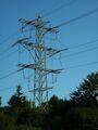
 Here, on the right the phases are rotated; on the left, two phases are swapped, thus the rotation sense changed.
 -
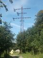
 Transposition tower. On the right side, the phases are rotated upward, on the left side downward.
 -
 Transposition in the span field of a 420 kV-line in Sweden


-
 Transposition on a single-phase line
 -
 Transposition by using multiple towers
 -
 Transposition by using elongated traverses


-
 154 kV double-circuit transposition tower.

See also
- Suspension tower
- Dead-end tower
External links
- ↑ Technology, Electrical (2024-04-15). "Why are Conductor Positions Swapped in a Transposition Tower?" (in en-US). https://www.electricaltechnology.org/2024/04/transposition-tower-position-overhead-conductor-exchanged.html/amp.
- ↑ O Donovan, Michael; Barry, Noel; Connell, Joe; Cowhey, Eoin (2021-04-02). "Mutual Coupling Compensation Techniques Used for Distance Protection of Parallel Lines" (in en). Energies 14 (7): 1982. doi:10.3390/en14071982. ISSN 1996-1073.
- ↑ "Inductive Coordination | The Song of the Open Wire" (in en-US). https://the-electric-orphanage.com/wp-inductive-coordination/.
 |  |
