Physics:Wave impedance
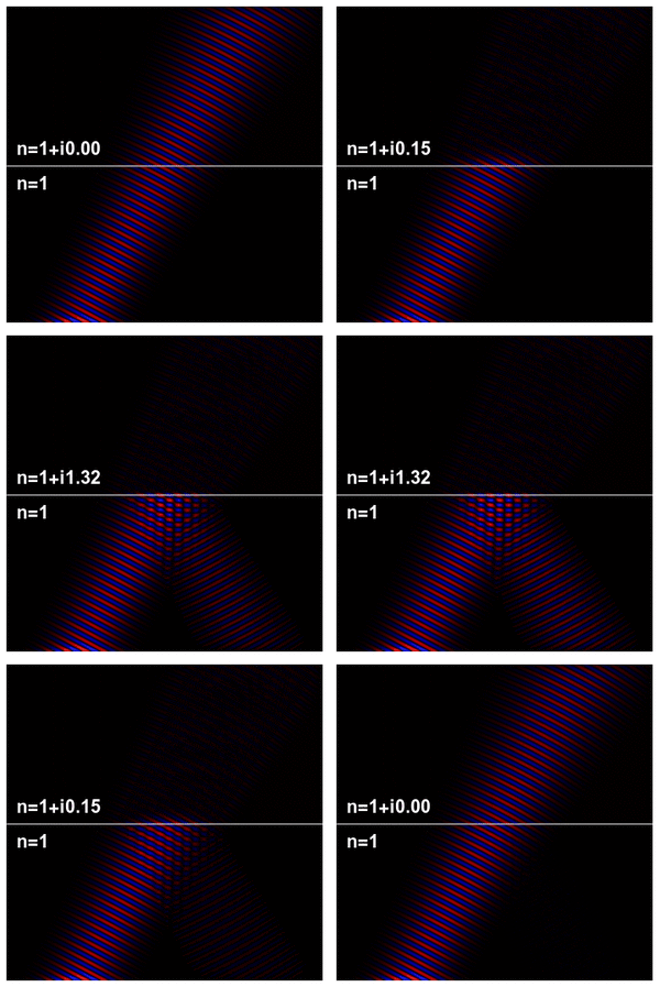
The wave impedance of an electromagnetic wave is the ratio of the transverse components of the electric and magnetic fields (the transverse components being those at right angles to the direction of propagation). For a transverse-electric-magnetic (TEM) plane wave traveling through a homogeneous medium, the wave impedance is everywhere equal to the intrinsic impedance of the medium. In particular, for a plane wave travelling through empty space, the wave impedance is equal to the impedance of free space. The symbol Z is used to represent it and it is expressed in units of ohms. The symbol η (eta) may be used instead of Z for wave impedance to avoid confusion with electrical impedance.
Definition

The wave impedance is given by
where is the electric field and is the magnetic field, in phasor representation. The impedance is, in general, a complex number.
In terms of the parameters of an electromagnetic wave and the medium it travels through, the wave impedance is given by
where μ is the magnetic permeability, ε is the (real) electric permittivity and σ is the electrical conductivity of the material the wave is travelling through (corresponding to the imaginary component of the permittivity multiplied by omega). In the equation, j is the imaginary unit, and ω is the angular frequency of the wave. Just as for electrical impedance, the impedance is a function of frequency. In the case of an ideal dielectric (where the conductivity is zero), the equation reduces to the real number
In free space
In free space the wave impedance of plane waves is:
(where ε0 is the permittivity constant in free space and μ0 is the permeability constant in free space). Now, since
- (by the SI definition of the metre),
- .
Hence the value essentially depends on . Until May 20th, 2019, , hence
- .
The currently accepted value of is
- .
In an unbounded dielectric
In an isotropic, homogeneous dielectric with negligible magnetic properties, i.e. H/m and F/m. So, the value of wave impedance in a perfect dielectric is
- ,
where is the relative dielectric constant.
In a waveguide
For any waveguide in the form of a hollow metal tube, (such as rectangular guide, circular guide, or double-ridge guide), the wave impedance of a travelling wave is dependent on the frequency , but is the same throughout the guide. For transverse electric (TE) modes of propagation the wave impedance is:[1]
where fc is the cut-off frequency of the mode, and for transverse magnetic (TM) modes of propagation the wave impedance is:[1]
Above the cut-off (f > fc), the impedance is real (resistive) and the wave carries energy. Below cut-off the impedance is imaginary (reactive) and the wave is evanescent. These expressions neglect the effect of resistive loss in the walls of the waveguide. For a waveguide entirely filled with a homogeneous dielectric medium, similar expressions apply, but with the wave impedance of the medium replacing Z0. The presence of the dielectric also modifies the cut-off frequency fc.
For a waveguide or transmission line containing more than one type of dielectric medium (such as microstrip), the wave impedance will in general vary over the cross-section of the line.
See also
- Characteristic impedance
- Impedance (disambiguation)
- Impedance of free space
References
 |
