YUV


YUV is a color model typically used as part of a color image pipeline. It encodes a color image or video taking human perception into account, allowing reduced bandwidth for chrominance components, compared to a "direct" RGB-representation. Historically, the terms YUV and Y′UV were used for a specific analog encoding of color information in television systems.[1] Today, the term YUV is commonly used in the computer industry to describe colorspaces that are encoded using YCbCr.
The YUV model defines one luminance component (Y) meaning physical linear-space brightness, and two chrominance components, called U (blue projection) and V (red projection) respectively. It can be used to convert to and from the RGB model, and with different color spaces.
The closely related Y′UV model uses the luma component (Y′) – nonlinear perceptual brightness, with the prime symbols (') denoting gamma correction.[2] Y′UV is used in the PAL analogue color TV standard (excluding PAL-N). Previous black-and-white systems used only luma (Y′) information. Color information (U and V) was added separately via a subcarrier so that a black-and-white receiver would still be able to receive and display a color picture transmission in the receiver's native black-and-white format, with no need for extra transmission bandwidth.
As for etymology, Y, Y′, U, and V are not abbreviations. The use of the letter Y for luminance can be traced back to the choice of XYZ primaries. This lends itself naturally to the usage of the same letter in luma (Y′), which approximates a perceptually uniform correlate of luminance. Likewise, U and V were chosen to differentiate the U and V axes from those in other spaces, such as the x and y chromaticity space. See the equations below or compare the historical development of the math.[3][4][5]
Related color models
The scope of the terms Y′UV, YUV, YCbCr, YPbPr, etc., is sometimes ambiguous and overlapping.
Historically, YUV and Y′UV were used for referring to analog television systems. But the same designation is sometimes applied to YCbCr, used for digital encoding of color information suited for video and image compression and transmission formats such as MPEG and JPEG.[6] Likewise, the YPbPr color model used in analog component video is sometimes called Y′UV. On these color models CB/PB and CR/PR are deviations from grey on blue–yellow and red–cyan axes, whereas on YUV U and V are blue–luminance and red–luminance differences respectively.
The Y′IQ color model used in the analog NTSC television broadcasting system also broadly follows the same principles as YUV, although in a more complex way. The YDbDr color model, used in the analog SECAM and PAL-N television broadcasting systems, is also related.
History
Y′UV was invented when engineers wanted color television in a black-and-white infrastructure.[7] They needed a signal transmission method that was compatible with black-and-white (B&W) TV while being able to add color. The luma component already existed as the black and white signal; they added the UV signal to this as a solution.
The UV representation of chrominance was chosen over straight R and B signals because U and V are color difference signals. In other words, the U and V signals tell the television to shift the color of a certain spot without altering its brightness. Or the U and V signals tell the monitor to make one color brighter at the cost of the other and by how much it should be shifted. The higher (or the lower when negative) the U and V values are, the more saturated (colorful) the spot gets. The closer the U and V values get to zero, the lesser it shifts the color meaning that the red, green and blue lights will be more equally bright, producing a greyer spot. This is the benefit of using color difference signals, i.e. instead of telling how much red there is to a color, it tells by how much it is more red than green or blue. In turn this meant that when the U and V signals would be zero or absent, it would just display a greyscale image. If R and B were to have been used, these would have non-zero values even in a B&W scene, requiring all three data-carrying signals. This was important in the early days of color television, because old black and white TV signals had no U and V signals present, meaning the color TV would just display it as B&W TV out of the box. In addition, black and white receivers could take the Y′ signal and ignore the U- and V-color signals, making Y′UV backward-compatible with all existing black-and-white equipment, input and output. If the color-TV standard wouldn't have used color difference signals, it could mean a color TV would make funny colors out of a B&W broadcast or it would need additional circuitry to translate the B&W signal to color. It was necessary to assign a narrower bandwidth to the chrominance channel because there was no additional bandwidth available. If some of the luminance information arrived via the chrominance channel (as it would have if RB signals were used instead of differential UV signals), B&W resolution would have been compromised.[8]
Conversion to/from RGB
SDTV with BT.470
Y′UV signals are typically created from RGB (red, green and blue) source. Weighted values of R, G, and B are summed to produce Y′, a measure of overall brightness or luminance. U and V are computed as scaled differences between Y′ and the B and R values.
PAL (NTSC used YIQ, which is further rotated) standard defines the following constants,[9] derived from BT.470 System M primaries and white point using SMPTE RP 177 (same constants called matrix coefficients were used later in BT.601, although it uses 1/2 instead of 0.436 and 0.615):
PAL signals in Y′UV are computed from R'G'B' (only SECAM IV used linear RGB[10]) as follows:
The resulting ranges of Y′, U, and V respectively are [0, 1], [−Umax, Umax], and [−Vmax, Vmax].
Inverting the above transformation converts Y′UV to RGB:
Equivalently, substituting values for the constants and expressing them as matrices gives these formulas for BT.470 System M (PAL):
For small values of Y' it is possible to get R, G, or B values that are negative so in practice we clamp the RGB results to the interval [0,1] or more correctly clamp inside the Y'CbCr.
In BT.470 a mistake was made (because 0.115 was used instead of 0.114 for blue and 0.493 was the result instead of 0.492). In practice that did not affect the decoders because the approximation 1/2.03 was used.[11]
HDTV with BT.709

For HDTV the ATSC decided to change the basic values for WR and WB compared to the previously selected values in the SDTV system. For HDTV these values are provided by Rec. 709. This decision further impacted on the matrix for the Y′UV↔RGB conversion so that its member values are also slightly different. As a result, with SDTV and HDTV there are generally two distinct Y′UV representations possible for any RGB triple: a SDTV-Y′UV and an HDTV-Y′UV one. This means in detail that when directly converting between SDTV and HDTV, the luma (Y′) information is roughly the same but the representation of the chroma (U & V) channel information needs conversion. Still in coverage of the CIE 1931 color space the Rec. 709 color space is almost identical to Rec. 601 and covers 35.9%.[12] In contrast to this UHDTV with Rec. 2020 covers a much larger area and thus its very own matrix was derived for YCbCr (no YUV/Y′UV, since decommissioning of analog TV).
BT.709 defines these weight values:
The and values are from above.
The conversion matrices for analog form of BT.709 are these, but there is no evidence those were ever used in practice (instead only actually described form of BT.709 is used, the YCbCr form):
Notes
- The weights used to compute Y′ (top row of matrix) are identical to those used in the Y′IQ color space.
- Equal values of red, green and blue (i.e. levels of gray) yield 0 for U and V. Black, RGB=(0, 0, 0), yields YUV=(0, 0, 0). White, RGB=(1, 1, 1), yields YUV=(1, 0, 0).
- These formulas are traditionally used in analog televisions and equipment; digital equipment such as HDTV and digital video cameras use Y′CbCr.
- UV planes in a range of Y=[0,1] using the BT.709 matrix
-
 Y′ value of 0
 -
 Y′ value of 0.5
 -
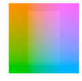 Y′ value of 0.5, with untruncated gamut shown by the center rectangle
 -
 Y′ value of 1


Numerical approximations
Prior to the development of fast SIMD floating-point processors, most digital implementations of RGB → Y′UV used integer math, in particular fixed-point approximations. Approximation means that the precision of the used numbers (input data, output data and constant values) is limited, and thus a precision loss of typically about the last binary digit is accepted by whoever makes use of that option in typically a trade-off to improved computation speeds.
In the following examples, the operator "" denotes a right shift of a by b binary positions. For clarification the variables are using two index characters: "u" is used for the unsigned final representation, and "t" is used for the scaled-down intermediate value. The examples below are given for BT.601 only. The same principle can be used for doing functionally equivalent operations using values that do an acceptable match for data that follows the BT.709 or any other comparable standard.
Y′ values are conventionally shifted and scaled to the range [16, 235] (referred to as studio swing or "TV levels") rather than using the full range of [0, 255] (referred to as full swing or "PC levels"). This practice was standardized in SMPTE-125M in order to accommodate signal overshoots ("ringing") due to filtering. The value 235 accommodates a maximal black-to-white overshoot of 255 − 235 = 20, or 20 / (235 − 16) = 9.1%, which is slightly larger than the theoretical maximal overshoot (Gibbs phenomenon) of about 8.9% of the maximal step. The toe-room is smaller, allowing only 16 / 219 = 7.3% overshoot, which is less than the theoretical maximal overshoot of 8.9%. This is why 16 is added to Y′ and why the Y′ coefficients in the basic transform sum to 220 instead of 255.[13] U and V values, which may be positive or negative, are summed with 128 to make them always positive, giving a studio range of 16–240 for U and V. (These ranges are important in video editing and production, since using the wrong range will result either in an image with "clipped" blacks and whites, or a low-contrast image.)
Studio swing for YCbCr BT.601
For getting the traditional "studio-swing" 8-bit representation of YCbCr for SDTV/BT.601 the following operations can be used:
- Basic transform from 8-bit RGB to 16-bit values (Y′: unsigned, Cb/Cr: signed, matrix values got rounded so that the later-on desired Y′ range of [16..235] and Cb/Cr range of [16..240] is reached):
- Scale down (">>8") to 8 bits with rounding ("+128") (Y′: unsigned, Cb/Cr: signed):
- Add an offset to the values to eliminate any negative values (all results are 8-bit unsigned):
Full swing for YCbCr BT.601
For getting a "full-swing" 8-bit representation of Y′CbCr for SDTV/BT.601 the following operations can be used:
- Basic transform from 8-bit RGB to 16-bit values (Y′: unsigned, Cb/Cr: signed, matrix values got rounded so that the later-on desired Y′CbCr range of each [0..255] is reached whilst no overflow can happen):
- Scale down (">>8") to 8-bit values with rounding ("+128") (Y′: unsigned, Cb/Cr: signed):
- Add an offset to the values to eliminate any negative values (all results are 8-bit unsigned):
Luminance/chrominance systems in general
The primary advantage of luma/chroma systems such as Y′UV, and its relatives Y′IQ and YDbDr, is that they remain compatible with black and white analog television (largely due to the work of Georges Valensi). The Y′ channel saves all the data recorded by black and white cameras, so it produces a signal suitable for reception on old monochrome displays. In this case, the U and V are simply discarded. If displaying color, all three channels are used, and the original RGB information can be decoded.
Another advantage of Y′UV is that some of the information can be discarded in order to reduce bandwidth. The human eye has fairly little spatial sensitivity to color: the accuracy of the brightness information of the luminance channel has far more impact on the image detail discerned than that of the other two. Understanding this human shortcoming, standards such as NTSC and PAL reduce the bandwidth of the chrominance channels considerably. (Bandwidth is in the temporal domain, but this translates into the spatial domain as the image is scanned out.)
Therefore, the resulting U and V signals can be substantially "compressed". In the NTSC (Y′IQ) and PAL systems, the chrominance signals had significantly narrower bandwidth than that for the luminance. Early versions of NTSC rapidly alternated between particular colors in identical image areas to make them appear adding up to each other to the human eye, while all modern analogue and even most digital video standards use chroma subsampling by recording a picture's color information at reduced resolution. Only half the horizontal resolution compared to the brightness information is kept (termed 4:2:2 chroma subsampling), and often the vertical resolution is also halved (giving 4:2:0). The 4:x:x standard was adopted due to the very earliest color NTSC standard which used a chroma subsampling of 4:1:1 (where the horizontal color resolution is quartered while the vertical is full resolution) so that the picture carried only a quarter as much color resolution compared to brightness resolution. Today, only high-end equipment processing uncompressed signals uses a chroma subsampling of 4:4:4 with identical resolution for both brightness and color information.
The I and Q axes were chosen according to bandwidth needed by human vision, one axis being that requiring the most bandwidth, and the other (fortuitously at 90 degrees) the minimum. However, true I and Q demodulation was relatively more complex, requiring two analog delay lines, and NTSC receivers rarely used it.
However, this color model conversion is lossy, particularly obvious in crosstalk from the luma to the chroma-carrying wire, and vice versa, in analogue equipment (including RCA connectors to transfer a digital signal, as all they carry is analogue composite video, which is either YUV, YIQ, or even CVBS). Furthermore, NTSC and PAL encoded color signals in a manner that causes high bandwidth chroma and luma signals to mix with each other in a bid to maintain backward compatibility with black and white television equipment, which results in dot crawl and cross color artifacts. When the NTSC standard was created in the 1950s, this was not a real concern since the quality of the image was limited by the monitor equipment, not the limited-bandwidth signal being received. However today's modern television is capable of displaying more information than is contained in these lossy signals. To keep pace with the abilities of new display technologies, attempts were made since the late 1970s to preserve more of the Y′UV signal while transferring images, such as SCART (1977) and S-Video (1987) connectors.
Instead of Y′UV, Y′CbCr was used as the standard format for (digital) common video compression algorithms such as MPEG-2. Digital television and DVDs preserve their compressed video streams in the MPEG-2 format, which uses a fully defined Y′CbCr color space, although retaining the established process of chroma subsampling. The professional CCIR 601 digital video format also uses Y′CbCr at the common chroma subsampling rate of 4:2:2, primarily for compatibility with previous analog video standards. This stream can be easily mixed into any output format needed.
Y′UV is not an absolute color space. It is a way of encoding RGB information, and the actual color displayed depends on the actual RGB colorants used to display the signal. Therefore, a value expressed as Y′UV is only predictable if standard RGB colorants are used (i.e. a fixed set of primary chromaticities, or particular set of red, green, and blue).
Furthermore, the range of colors and brightnesses (known as the color gamut and color volume) of RGB (whether it be BT.601 or Rec.709) is far smaller than the range of colors and brightnesses allowed by Y′UV. This can be very important when converting from Y′UV (or Y′CbCr) to RGB, since the formulas above can produce "invalid" RGB values – i.e., values below 0% or very far above 100% of the range (e.g., outside the standard 16–235 luma range (and 16–240 chroma range) for TVs and HD content, or outside 0–255 for standard definition on PCs). Unless these values are dealt with they will usually be "clipped" (i.e., limited) to the valid range of the channel affected. This changes the hue of the color, which is very undesirable, so it is therefore often considered better to desaturate the offending colors such that they fall within the RGB gamut.[14] Likewise, when RGB at a given bit depth is converted to YUV at the same bit depth, several RGB colors can become the same Y′UV color, resulting in information loss.
Relation with Y′CbCr
Y′UV is often used as a term for YCbCr. However, while related, they are different formats with different scale factors.[15] Not scaled matrix is used in Photo CD's PhotoYCC. U and V are bipolar signals which can be positive or negative, and are zero for greys, whereas YCbCr usually scales all channels to either the 16–235 range or the 0–255 range, which makes Cb and Cr unsigned quantities which are 128 for greys.
Nevertheless, the relationship between them in the standard case is simple. In particular, the Y' channels of both are linearly related to each other, both Cb and U are related linearly to (B-Y), and both Cr and V are related linearly to (R-Y).
Types of sampling
To get a digital signal, Y′UV images can be sampled in several different ways; see chroma subsampling.
Converting between Y′UV and RGB
RGB files are typically encoded in 8, 12, 16 or 24 bits per pixel. In these examples, we will assume 24 bits per pixel, which is written as RGB888. The standard byte format is:
r0, g0, b0, r1, g1, b1, ...
Y′UV files can be encoded in 12, 16 or 24 bits per pixel. The common formats are Y′UV444 (or YUV444), YUV411, Y′UV422 (or YUV422) and Y′UV420p (or YUV420). The apostrophe after the Y is often omitted, as is the "p" after YUV420p. In terms of actual file formats, YUV420 is the most common, as the data is more easily compressed, and the file extension is usually ".YUV".
The relation between data rate and sampling (A:B:C) is defined by the ratio between Y to U and V channel.[16][17]
To convert from RGB to YUV or back, it is simplest to use RGB888 and YUV444. For YUV411, YUV422 and YUV420, the bytes need to be converted to YUV444 first.
YUV444    3 bytes per pixel     (12 bytes per 4 pixels)
YUV422    4 bytes per 2 pixels   (8 bytes per 4 pixels)
YUV411    6 bytes per 4 pixels
YUV420p   6 bytes per 4 pixels, reordered
Y′UV444 to RGB888 conversion
The function [R, G, B] = Y′UV444toRGB888(Y′, U, V) converts Y′UV format to simple RGB format.
The RGB conversion formulae used for Y′UV444 format are also applicable to the standard NTSC TV transmission format of YUV420 (or YUV422 for that matter). For YUV420, since each U or V sample is used to represent 4 Y samples that form a square, a proper sampling method can allow the utilization of the exact conversion formulae shown below. For more details, please see the 4:2:0 format demonstration in the bottom section of this article.
These formulae are based on the NTSC standard:
On older, non-SIMD architectures, floating point arithmetic is much slower than using fixed-point arithmetic, so an alternative formulation is:[18]
For the conversion from Y'UV to RGB, using the coefficients c, d and e, and noting that denotes clamping a value to the 8-bit range of 0 to 255, the following formulae provide the conversion from Y′UV to RGB (NTSC version):
Note: The above formulae are actually implied for YCbCr. Though the term YUV is used here, YUV and YCbCr are not exactly the same in a strict manner.
The ITU-R version of the formula is different, with , whereas and above:
Integer operation of ITU-R standard for YCbCr (8 bits per channel) to RGB888:
Y′UV422 to RGB888 conversion
- Input: Read 4 bytes of Y′UV (u, y1, v, y2)
- Output: Writes 6 bytes of RGB (R, G, B, R, G, B)
u  = yuv[0];
y1 = yuv[1];
v  = yuv[2];
y2 = yuv[3];
Using this information it could be parsed as regular Y′UV444 format to get 2 RGB pixels info:
rgb1 = Y′UV444toRGB888(y1, u, v);
rgb2 = Y′UV444toRGB888(y2, u, v);

Y′UV422 can also be expressed with the values in an alternative order, e.g. for the FourCC format code YUY2.
- Input: Read 4 bytes of Y′UV (y1, u, y2, v), (y1, y2, u, v) or (u, v, y1, y2)
Y′UV411 to RGB888 conversion
- Input: Read 6 bytes of Y′UV
- Output: Writes 12 bytes of RGB
// Extract YUV components
u  = yuv[0];
y1 = yuv[1];
y2 = yuv[2];
v  = yuv[3];
y3 = yuv[4];
y4 = yuv[5];
rgb1 = Y′UV444toRGB888(y1, u, v);
rgb2 = Y′UV444toRGB888(y2, u, v);
rgb3 = Y′UV444toRGB888(y3, u, v);
rgb4 = Y′UV444toRGB888(y4, u, v);
So the result is we are getting 4 RGB pixels values (4*3 bytes) from 6 bytes. This means reducing the size of transferred data to half, with a loss of quality.
Y′UV420p (and Y′V12 or YV12) to RGB888 conversion
Y′UV420p is a planar format, meaning that the Y′, U, and V values are grouped together instead of interspersed. The reason for this is that by grouping the U and V values together, the image becomes much more compressible. When given an array of an image in the Y′UV420p format, all the Y′ values come first, followed by all the U values, followed finally by all the V values.
The Y′V12 format is essentially the same as Y′UV420p, but it has the U and V data switched: the Y′ values are followed by the V values, with the U values last. As long as care is taken to extract U and V values from the proper locations, both Y′UV420p and Y′V12 can be processed using the same algorithm.
As with most Y′UV formats, there are as many Y′ values as there are pixels. Where X equals the height multiplied by the width, the first X indices in the array are Y′ values that correspond to each individual pixel. However, there are only one fourth as many U and V values. The U and V values correspond to each 2 by 2 block of the image, meaning each U and V entry applies to four pixels. After the Y′ values, the next X/4 indices are the U values for each 2 by 2 block, and the next X/4 indices after that are the V values that also apply to each 2 by 2 block.

As shown in the above image, the Y′, U and V components in Y′UV420 are encoded separately in sequential blocks. A Y′ value is stored for every pixel, followed by a U value for each 2×2 square block of pixels, and finally a V value for each 2×2 block. Corresponding Y′, U and V values are shown using the same color in the diagram above. Read line-by-line as a byte stream from a device, the Y′ block would be found at position 0, the U block at position x×y (6×4 = 24 in this example) and the V block at position x×y + (x×y)/4 (here, 6×4 + (6×4)/4 = 30).
Y′UV420sp (NV21) to RGB conversion (Android)
This format (NV21) is the standard picture format on Android camera preview. YUV 4:2:0 planar image, with 8 bit Y samples, followed by interleaved V/U plane with 8bit 2x2 subsampled chroma samples.[19]
C++ code used on Android to convert pixels of YUVImage:[20]
void YUVImage::yuv2rgb(uint8_t yValue, uint8_t uValue, uint8_t vValue,
        uint8_t *r, uint8_t *g, uint8_t *b) const {
    int rTmp = yValue + (1.370705 * (vValue-128));
    // or fast integer computing with a small approximation
    // rTmp = yValue + (351*(vValue-128))>>8;
    int gTmp = yValue - (0.698001 * (vValue-128)) - (0.337633 * (uValue-128));
    // gTmp = yValue - (179*(vValue-128) + 86*(uValue-128))>>8;
    int bTmp = yValue + (1.732446 * (uValue-128));
    // bTmp = yValue + (443*(uValue-128))>>8;
    *r = clamp(rTmp, 0, 255);
    *g = clamp(gTmp, 0, 255);
    *b = clamp(bTmp, 0, 255);
}
References
- ↑ Poynton, Charles. "YUV and luminance considered harmful: A plea for precise terminology in video" [1]
- ↑ "EG 28:1993 - SMPTE Engineering Guideline - Annotated Glossary of Essential Terms for Electronic Production". Eg 28:1993: 1–45. May 1993. doi:10.5594/SMPTE.EG28.1993. ISBN 978-1-61482-022-2. https://ieeexplore.ieee.org/document/7291332.
- ↑ CIELUV
- ↑ CIE 1960 color space
- ↑ Macadam, David L. (1 August 1937). "Projective Transformations of I. C. I. Color Specifications". Journal of the Optical Society of America 27 (8): 294–297. doi:10.1364/JOSA.27.000294. Bibcode: 1937JOSA...27..294M. http://www.opticsinfobase.org/josa/abstract.cfm?uri=josa-27-8-294. Retrieved 12 April 2014.
- ↑ Poynton, Charles. "YUV and luminance considered harmful: A plea for precise terminology in video" [2]
- ↑ Maller, Joe. RGB and YUV Color, FXScript Reference
- ↑ W. Wharton & D. Howorth, Principles of Television Reception, Pitman Publishing, 1971, pp 161-163
- ↑ "BT.470: Conventional television systems". p. 9. https://www.itu.int/rec/R-REC-BT.470-6-199811-S/en.
- ↑ "World Analogue Television Standards and Waveforms". 2019-02-27. http://www.radios-tv.co.uk/Pembers/World-TV-Standards/Colour-Standards.html#SECAM.
- ↑ "ST 170:2004 - SMPTE Standard - For Television — Composite Analog Video Signal — NTSC for Studio Applications". St 170:2004: 1–21. November 2004. doi:10.5594/SMPTE.ST170.2004. ISBN 978-1-61482-335-3. https://ieeexplore.ieee.org/document/7291416.
- ↑ ""Super Hi-Vision" as Next-Generation Television and Its Video Parameters". Information Display. http://www.informationdisplay.org/article.cfm?year=2012&issue=12&file=art6.
- ↑ Jack, Keith (1993). Video Demystified. HighText Publications. ISBN 1-878707-09-4. https://archive.org/details/videodemystified00jack.
- ↑ Limiting of YUV digital video signals (BBC publication) Authors: V.G. Devereux http://downloads.bbc.co.uk/rd/pubs/reports/1987-22.pdf
- ↑ Poynton, Charles (19 June 1999). YUV and luminance considered harmful. http://www.poynton.com/PDFs/YUV_and_luminance_harmful.pdf. Retrieved 18 November 2016.
- ↑ msdn.microsoft.com, Recommended 8-Bit YUV Formats for Video Rendering
- ↑ msdn.microsoft.com, YUV Video Subtypes
- ↑ "Converting Between YUV and RGB (Windows CE .NET 4.2)". https://msdn.microsoft.com/en-us/library/ms893078.aspx.
- ↑ fourcc.com YUV pixel formas
- ↑ "Media/Libstagefright/Yuv/YUVImage.CPP - platform/Frameworks/Av - Git at Google". https://android.googlesource.com/platform/frameworks/av/+/0e4e5a8/media/libstagefright/yuv/YUVImage.cpp.
External links
- Explanation of many different formats in the Y′UV family
- Poynton, Charles. Video engineering
- Colorlab MATLAB toolbox for color science computation and accurate color reproduction (by Jesus Malo and Maria Jose Luque, Universitat de Valencia). It includes CIE standard tristimulus colorimetry and transformations to a number of non-linear color appearance models (CIE Lab, CIE CAM, etc.).
- Kohn, Mike. Y′UV422 to RGB using SSE/Assembly
- YUV, YCbCr, YPbPr color space and models
- Color formats for image and video processing – Color conversion between RGB, YUV, YCbCr and YPbPr
- libyuv
- pixfc-sse – C library of SSE-optimized color format conversions
- YUV files – Sample / Demo YUV/RGB video files in many YUV formats, help you for the testing.
- hacktv – library for analog TV transmission using software-defined radio
| CAM | |
|---|---|
| CIE | |
| RGB | |
| YUV | |
| Other | |
| Color systems and standards | |
For the vision capacities of organisms or machines, see | |
 |
