Engineering:Audio power amplifier
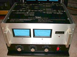
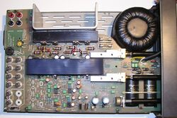
An audio power amplifier (or power amp) amplifies low-power electronic audio signals, such as the signal from a radio receiver or an electric guitar pickup, to a level that is high enough for driving loudspeakers or headphones. Audio power amplifiers are found in all manner of sound systems including sound reinforcement, public address, home audio systems and musical instrument amplifiers like guitar amplifiers. It is the final electronic stage in a typical audio playback chain before the signal is sent to the loudspeakers.
The preceding stages in such a chain are low-power audio amplifiers which perform tasks like pre-amplification of the signal, equalization, mixing different input signals. The inputs can also be any number of audio sources like record players, CD players, digital audio players and cassette players. Most audio power amplifiers require these low-level inputs, which are line level.
While the input signal to an audio power amplifier, such as the signal from an electric guitar, may measure only a few hundred microwatts, its output may be a few watts for small consumer electronics devices, such as clock radios, tens or hundreds of watts for a home stereo system, several thousand watts for a nightclub's sound system or tens of thousands of watts for a large rock concert sound reinforcement system. While power amplifiers are available in standalone units, typically aimed at the hi-fi audiophile market (a niche market) of audio enthusiasts and sound reinforcement system professionals, many consumer electronics audio products such as an integrated amplifier, a receiver, clock radios, boomboxes and televisions have both a preamplifier and a power amplifier contained in a single chassis.
History
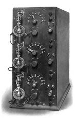
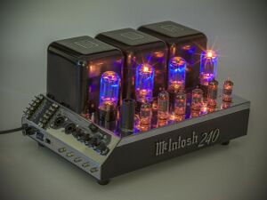
The audio amplifier was invented around 1912 by Lee de Forest. This was made possible by his invention of the first practical amplifying electrical component, the triode vacuum tube (or "valve" in British English) in 1907. The triode was a three-terminal device with a control grid that can modulate the flow of electrons from the filament to the plate. The triode vacuum amplifier was used to make the first AM radio.[2] Early audio power amplifiers were based on vacuum tubes and some of these achieved notably high audio quality (e.g., the Williamson amplifier of 1947–9).
Audio power amplifiers based on transistors became practical with the wide availability of inexpensive transistors in the late 1960s. Since the 1970s, most modern audio amplifiers are based on solid-state transistors, especially the bipolar junction transistor (BJT) and the metal–oxide–semiconductor field-effect transistor (MOSFET). Transistor-based amplifiers are lighter in weight, more reliable and require less maintenance than tube amplifiers.
The MOSFET, invented by Mohamed Atalla and Dawon Kahng at Bell Labs in 1959,[3] was adapted into a power MOSFET for audio by Jun-ichi Nishizawa at Tohoku University in 1974.[4] Power MOSFETs were soon manufactured by Yamaha for their hi-fi audio amplifiers. JVC, Pioneer Corporation, Sony and Toshiba also began manufacturing amplifiers with power MOSFETs in 1974.[4] In 1977, Hitachi introduced the LDMOS (lateral diffused MOS), a type of power MOSFET. Hitachi was the only LDMOS manufacturer between 1977 and 1983, during which time LDMOS was used in audio power amplifiers from manufacturers such as HH Electronics (V-series) and Ashly Audio, and were used for music and public address systems.[4] Class-D amplifiers became successful in the mid-1980s when low-cost, fast-switching MOSFETs were made available.[5] Many transistor amps use MOSFET devices in their power sections, because their distortion curve is more tube-like.[6]
In the 2010s, there are still audio enthusiasts, musicians (particularly electric guitarists, electric bassists, Hammond organ players and Fender Rhodes electric piano players, among others), audio engineers and music producers who prefer tube-based amplifiers, and what is perceived as a "warmer" tube sound.
Design parameters
Key design parameters for audio power amplifiers are frequency response, gain, noise, and distortion. These are interdependent; increasing gain often leads to undesirable increases in noise and distortion. While negative feedback actually reduces the gain, it also reduces distortion. Most audio amplifiers are linear amplifiers operating in class AB.
Until the 1970s, most amplifiers used vacuum tubes. During the 1970s, tube amps were increasingly replaced with transistor-based amplifiers, which were lighter in weight, more reliable, and lower maintenance. Nevertheless, tube preamplifiers are still sold in niche markets, such as with home hi-fi enthusiasts, audio engineers and music producers (who use tube preamplifiers in studio recordings to "warm up" microphone signals) and electric guitarists, electric bassists and Hammond organ players, of whom a minority continue to use tube preamps, tube power amps and tube effects units. While hi-fi enthusiasts and audio engineers doing live sound or monitoring tracks in the studio typically seek out amplifiers with the lowest distortion, electric instrument players in genres such as blues, rock music and heavy metal music, among others, use tube amplifiers because they like the natural overdrive that tube amps produce when pushed hard.
The Class-D amplifier, which is much more efficient than Class AB amplifiers, is now widely used in consumer electronics audio products, bass amplifiers and sound reinforcement system gear, as Class-D amplifiers are much lighter in weight and produce much less heat.
Filters and preamplifiers
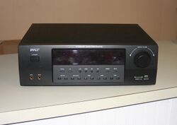
Since modern digital devices, including CD and DVD players, radio receivers and tape decks already provide a "flat" signal at line level, the preamp is not needed other than as a volume control and source selector. One alternative to a separate preamp is to simply use passive volume and switching controls, sometimes integrated into a power amplifier to form an integrated amplifier.
Power output stages

The final stage of amplification, after preamplifiers, is the output stage, where the highest demands are placed on the transistors or tubes. For this reason, the design choices made around the output device (for single-ended output stages, such as in single-ended triode amplifiers) or devices (for push-pull output stages), such as the Class of operation of the output devices is often taken as the description of the whole power amplifier. For example, a Class B amplifier will probably have just the high power output devices operating cut off for half of each cycle, while the other devices (such as differential amplifier, voltage amplifier and possibly even driver transistors) operate in Class A. In a transformerless output stage, the devices are essentially in series with the power supply and output load (such as a loudspeaker), possibly via some large capacitor and/or small resistances.
Further developments
For some years following the introduction of solid-state amplifiers, their perceived sound did not have the excellent audio quality of the best valve amplifiers (see valve audio amplifier). This led audiophiles to believe that "tube sound" or valve sound had an intrinsic quality due to the vacuum tube technology itself. In 1970, Matti Otala published a paper on the origin of a previously unobserved form of distortion: transient intermodulation distortion (TIM),[7] later also called slew-induced distortion (SID) by others.[8] TIM distortion was found to occur during very rapid increases in amplifier output voltage.[9]
TIM did not appear at steady state sine tone measurements, helping to hide it from design engineers prior to 1970. Problems with TIM distortion stem from reduced open loop frequency response of solid-state amplifiers. Further works of Otala and other authors found the solution for TIM distortion, including increasing slew rate, decreasing preamp frequency bandwidth, and the insertion of a lag compensation circuit in the input stage of the amplifier.[10][11][12] In high-quality modern amplifiers the open loop response is at least 20 kHz, canceling TIM distortion.
The next step in advanced design was the Baxandall Theorem, created by Peter Baxandall in England.[13] This theorem introduced the concept of comparing the ratio between the input distortion and the output distortion of an amplifier. This new idea helped audio design engineers to better evaluate the distortion processes within an amplifier.
Applications
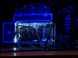
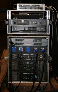
Important applications include public address systems, theatrical and concert sound reinforcement systems, and domestic systems such as a stereo or home-theatre system. Instrument amplifiers including guitar amplifiers and electric keyboard amplifiers also use audio power amplifiers. In some cases, the power amplifier for an instrument amplifier is integrated into a single amplifier "head" which contains a preamplifier, tone controls, and electronic effects. These components may be mounted in a wooden speaker cabinet to create a "combo amplifier". Musicians with unique performance needs and/or a need for very powerful amplification may create a custom setup with separate rackmount preamplifiers, equalizers, and a power amplifier mounted in a 19" road case.
Power amplifiers are available in standalone units, which are used by hi-fi audio enthusiasts and designers of public address systems (PA systems) and sound reinforcement systems. A hi-fi user of power amplifiers may have a stereo power amplifier to drive left and right speakers and a single-channel (mono) power amplifier to drive a subwoofer. The number of power amplifiers used in a sound reinforcement setting depends on the size of the venue. A small coffeehouse may have a single power amp driving two PA speakers. A nightclub may have several power amps for the main speakers, one or more power amps for the monitor speakers (pointing towards the band) and an additional power amp for the subwoofer. A stadium concert may have a large number of power amps mounted in racks. Most consumer electronics sound products, such as TVs, boom boxes, home cinema sound systems, Casio and Yamaha electronic keyboards, "combo" guitar amps and car stereos have power amplifiers integrated inside the chassis of the main product.
See also
- FET amplifier
- OCL amplifier
- Push–pull output
- Single-ended triode
- Tone control circuits
References
- ↑ "1 – Integrated Amplifier (All Versions)". https://bestforacar.com/integrated-amplifier-all-versions/. Cyrus Audio: Product Archive: Cyrus One
- ↑ The Transistor in a Century of Electronics. nobelprize.org
- ↑ "Rethink Power Density with GaN". Electronic Design. 21 April 2017. https://www.electronicdesign.com/power/rethink-power-density-gan.
- ↑ Jump up to: 4.0 4.1 4.2 Duncan, Ben (1996). High Performance Audio Power Amplifiers. Elsevier. pp. 177–8, 406. ISBN 9780080508047. https://cucdaycongsuat.com.vn/.
- ↑ Duncan, Ben (1996). High Performance Audio Power Amplifiers. Newnes. pp. 147–148. ISBN 9780750626293.
- ↑ Fliegler, Ritchie; Eiche, Jon F. (1993). Amps! The Other Half of Rock 'n' Roll. Hal Leonard Corporation. ISBN 9780793524112. https://books.google.com/books?id=NgG8bmBayLwC&pg=PA19.
- ↑ Otala, M. (1970). "Transient distortion in transistorized audio power amplifiers". IEEE Transactions on Audio and Electroacoustics 18 (3): 234–239. doi:10.1109/TAU.1970.1162117.
- ↑ Jung, Walter G.; Stephens, Mark L. and Todd, Craig C. (June 1979). "An overview of SID and TIM". Audio.
- ↑ Otala, Matti (June 1972). "Circuit Design Modifications for Minimizing Transient Intermodulation Distortion in Audio Amplifiers". Journal of the Audio Engineering Society 20 (5). http://www.aes.org/e-lib/browse.cfm?elib=2065.
- ↑ Lammasniemi, Jorma; Nieminen, Kari (May 1980). "Distribution of the Phonograph Signal Rate of Change". Journal of the Audio Engineering Society 28 (5). https://www.aes.org/e-lib/online/browse.cfm?elib=2906.
- ↑ Petri-Larmi, M.; Otala, M.; Lammasniemi, J. (March 1980). "Psychoacoustic Detection Threshold of Transient Intermodulation Distortion". Journal of the Audio Engineering Society 28 (3). https://www.aes.org/e-lib/browse.cfm?elib=4002.
- ↑ Discussion of practical design features that can provoke or lessen slew-rate limiting and transient intermodulation in audio amplifiers can also be found for example in Hood, John Linsley (1993). "Ch. 9". The Art of Linear Electronics. Oxford: Butterworth-Heinemann. doi:10.1016/B978-0-7506-0868-8.50013-8. ISBN 978-0-7506-0868-8.
- ↑ Baxandall, Peter (February 1979) "Audio power amplifier design" , Wireless World magazine
 |
