Physics:FlowFET
A flowFET is a microfluidic component which allows the rate of flow of liquid in a microfluidic channel to be modulated by the electrical potential applied to it. In this way, it behaves as a microfluidic analogue to the field effect transistor,[1] except that in the flowFET the flow of liquid takes the place of the flow of electric current. Indeed, the name of the flowFET is derived from the naming convention of electronic FETs (e.g. MOSFET, FINFET etc.).
Mechanism of action

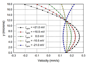
A flowFET relies on the principle of electro-osmotic flow (EOF). In many liquid-solid interfaces, there is an electrical double layer that develops due to interactions between the two phases. In the case of a microfluidic channel, this results in a charged layer of liquid on the periphery of the fluid column which surrounds the bulk of the liquid. This electric double layer has an associated potential difference known as the zeta potential. When an appropriately-oriented electrical field is applied to this interfacial double layer (i.e. parallel to the channel and in the plane of the electric double layer), the charged liquid ions experience a motive Lorentz force. Since this layer sheaths the fluid column, and since this layer moves, the entire column of liquid will begin to move with a speed [math]\displaystyle{ \nu_{EOF} }[/math]. The velocity of the fluid layer "diffuses" into the bulk of the channel from the periphery towards the centre due to viscous coupling.[1] The speed is related to the strength of the electric field [math]\displaystyle{ E }[/math], the magnitude of the zeta potential [math]\displaystyle{ \zeta }[/math], the permittivity [math]\displaystyle{ \epsilon }[/math] and the viscosity [math]\displaystyle{ \eta }[/math] of the fluid:[1]
[math]\displaystyle{ \nu_{EOF}={\epsilon \over \eta} \zeta E }[/math]
In a FlowFET, the zeta potential between the channel walls and the fluid can be altered by applying an electrical field perpendicular to the channel walls. This has the effect of altering the motive force experienced by the mobile liquid atoms in the double layer. This change in the zeta-potential can be used to control both the magnitude and direction of the electro-osmotic flow in the microchannel.[1]
The controlling voltage need only be in the range of 50 V for a typical microfluidic channel,[2] since this correlates to a gradient of 1.5 MV/cm due to the channel size.[1]
Operational limitations
Variation of the FlowFET dimensions (e.g. insulating layer thickness between the channel wall and gate electrode) due to the manufacturing process can lead to inexact control of the zeta potential. This can be exacerbated in the case of wall contamination, which can alter the channel wall surface's electrical properties adjacent to the gate electrode. This will affect the local flow characteristics, which may be especially important in chemical synthesis systems whose stoichiometry are directly related to the transport rate of reaction precursors and reaction products.[2]
There are constraints placed on the fluid that can be manipulated in a FlowFET. Since it relies on EOF, only fluids producing an EOF in response to an applied electric field may be used.[2]
While the controlling voltage need only be on the order of 50V,[2] the EOF-producing voltage along the channel axis is larger, on the order of 300V.[3] It is noticed experimentally that electrolysis may occur at the electrode contacts. This water electrolysis can alter the pH in the channel and adversely affect biological cells and biomolecules, while gas bubbles tend to "clog" microfluidic systems.[4]
In further analogy with microelectronic systems, the switching time for a flowFET is inversely proportional to its size. Scaling down a flowFET results in a reduction in the amount of time for the flow to equilibrate to a new flow rate following a change in the applied electrical field. It should be noted, however, that the frequency of flowFET is many orders of magnitude slower than with an electronic FET.
Applications
A FlowFET sees potential uses in massively parallel microfluidic manipulation,[1] for example in DNA microarrays.[2]
Without using a FlowFET, it is necessary to control the rate of EOF by changing the magnitude of the EOF-producing field (i.e. the field parallel to the channel's axis) while leaving the zeta potential unaltered. In this arrangement, however, simultaneous control of EOF in channels connected with each other cannot easily be accomplished.[1]
A FlowFET provides a way of controlling microfluidic flow in a way that uses no moving parts.[1][2][3] This is in stark contrast to other solutions including pneumatically-actuated peristaltic pumps such as presented by Wu et al.[5] Fewer moving parts allows less opportunity for mechanical breakdown of a microfluidic device. This may be increasingly relevant as large future iterations of large microelectronic fluidic (MEF) arrays continue to increase in size and complexity.
The use of bi-directional electronically-controlled flow has interesting options for particle and bubble cleaning operations.[2]
See also
References
- ↑ 1.0 1.1 1.2 1.3 1.4 1.5 1.6 1.7 Schasfoort, Richard B. M.; Schlautmann, Stefan; Hendrikse, Jan; van den Berg, Albert (29 October 1999). "Field-Effect Flow Control for Microfabricated Fluidic Networks". Science 286 (5441): 942–945. doi:10.1126/science.286.5441.942. PMID 10542145. https://ris.utwente.nl/ws/files/6645318/Schasfoort99field.pdf.
- ↑ 2.0 2.1 2.2 2.3 2.4 2.5 2.6 2.7 Kerkhoff, H.G.; Barber, R.W.; Zhang, X.; Emerson, D.R. (2006). "Fault modelling and co-simulation in FlowFET-based biological array systems". Proceedings – Third IEEE International Workshop on Electronic Design, Test and Applications, DELTA 2006: 177–182.
- ↑ 3.0 3.1 Kerkhoff, H; Barber, R; Emerson, D; Van Der Wouden, E (2005). "Design and Test of Micro-Electronic Fluidic Systems". Proceedings Workshop on MEMS, DATE05 Workshops: 47–52.
- ↑ Erlandsson, P. G.; Robinson, N. D. (2011). "Electrolysis-reducing electrodes for electrokinetic devices". Electrophoresis 32 (6–7): 784–790. doi:10.1002/elps.201000617. PMID 21425174. http://urn.kb.se/resolve?urn=urn:nbn:se:liu:diva-67312.
- ↑ Wu, Min Hsien; Huang, Song Bin; Cui, Zhanfeng; Cui, Zheng; Lee, Gwo Bin (2008). "Development of perfusion-based micro 3-D cell culture platform and its application for high throughput drug testing". Sensors and Actuators, B: Chemical 129 (1): 231–240. doi:10.1016/j.snb.2007.07.145.
 |

